Facebook
 Google
 GitHub
 Linkedin
AC Electric Circuits
Series and Parallel AC Circuits
75 questions By Tony R. Kuphaldt
-
Question 22 of 75
One way to vary the amount of power delivered to a resistive AC load is by varying another resistance connected in series:

A problem with this power control strategy is that power is wasted in the series resistance (I2Rseries). A different strategy for controlling power is shown here, using a series inductance rather than resistance:

Explain why the latter circuit is more power-efficient than the former, and draw a phasor diagram showing how changes in Lseries affect Ztotal.
Reveal answerInductors are reactive rather than resistive components, and therefore do not dissipate power (ideally).

Follow-up question: the inductive circuit is not just more energy-efficient - it is safer as well. Identify a potential safety hazard that the resistive power-control circuit poses due to the energy dissipation of its variable resistor.
Notes:If appropriate, you may want to mention devices called saturable reactors, which are used to control power in AC circuits by the exact same principle: varying a series inductance.
-
Question 23 of 75
A quantity sometimes used in DC circuits is conductance, symbolized by the letter G. Conductance is the reciprocal of resistance (G = 1/R), and it is measured in the unit of siemens.
Expressing the values of resistors in terms of conductance instead of resistance has certain benefits in parallel circuits. Whereas resistances (R) add in series and “diminish” in parallel (with a somewhat complex equation), conductances (G) add in parallel and “diminish” in series. Thus, doing the math for series circuits is easier using resistance and doing math for parallel circuits is easier using conductance:

In AC circuits, we also have reciprocal quantities to reactance (X) and impedance (Z). The reciprocal of reactance is called susceptance (B = 1/X), and the reciprocal of impedance is called admittance (Y = 1/Z). Like conductance, both these reciprocal quantities are measured in units of siemens.
Write an equation that solves for the admittance (Y) of this parallel circuit. The equation need not solve for the phase angle between voltage and current, but merely provide a scalar figure for admittance (in siemens):

Reveal answerYtotal = √{G2 B2}
Follow-up question #1: draw a phasor diagram showing how Y, G, and B relate.
Follow-up question #2: re-write this equation using quantities of resistance (R), reactance (X), and impedance (Z), instead of conductance (G), susceptance (B), and admittance (Y).
Notes:Ask your students if this equation looks familiar to them. It should!
The answer to the second follow-up question is a matter of algebraic substitution. Work through this process with your students, and then ask them to compare the resulting equation with other equations they’ve seen before. Does its form look familiar to them in any way?
-
Question 24 of 75
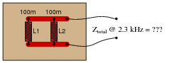
Calculate the total impedance for these two 100 mH inductors at 2.3 kHz, and draw a phasor diagram showing circuit admittances (Ytotal, G, and B):
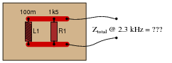
Now, re-calculate impedance and re-draw the phasor admittance diagram supposing the second inductor is replaced by a 1.5 kΩ resistor:
Reveal answer

Challenge question: why are the susceptance vectors (BL1 and BL2) pointed down instead of up as impedance vectors for inductances typically are?
Notes:Phasor diagrams are powerful analytical tools, if one knows how to draw and interpret them. With hand calculators being so powerful and readily able to handle complex numbers in either polar or rectangular form, there is temptation to avoid phasor diagrams and let the calculator handle all the angle manipulation. However, students will have a much better understanding of phasors and complex numbers in AC circuits if you hold them accountable to representing quantities in that form.