Facebook
 Google
 GitHub
 Linkedin
Analog Integrated Circuits
Summer and Subtractor OpAmp Circuits
25 questions By Tony R. Kuphaldt
-
Question 22 of 25
Predict how the operation of this summer circuit will be affected as a result of the following faults. Consider each fault independently (i.e. one at a time, no multiple faults):
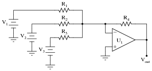
- Resistor R1 fails open:
- Resistor R2 fails open:
- Solder bridge (short) across resistor R3:
- Resistor R4 fails open:
- Solder bridge (short) across resistor R4:
For each of these conditions, explain why the resulting effects will occur.
Reveal answer- Resistor R1 fails open: Vout becomes (inverted) sum of V2 and V3 only.
- Resistor R2 fails open: Vout becomes (inverted) sum of V1 and V3 only.
- Solder bridge (short) across resistor R3: Vout saturates in a negative direction.
- Resistor R4 fails open: Vout saturates in a negative direction.
- Solder bridge (short) across resistor R4: Vout goes to 0 volts.
Notes:The purpose of this question is to approach the domain of circuit troubleshooting from a perspective of knowing what the fault is, rather than only knowing what the symptoms are. Although this is not necessarily a realistic perspective, it helps students build the foundational knowledge necessary to diagnose a faulted circuit from empirical data. Questions such as this should be followed (eventually) by other questions asking students to identify likely faults based on measurements.
-
Question 23 of 25
Predict how the operation of this difference amplifier circuit will be affected as a result of the following faults. Consider each fault independently (i.e. one at a time, no multiple faults):
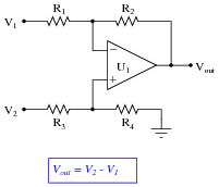
- Resistor R1 fails open:
- Resistor R2 fails open:
- Solder bridge (short) across resistor R3:
- Resistor R4 fails open:
- Solder bridge (short) across resistor R4:
For each of these conditions, explain why the resulting effects will occur.
Reveal answer- Resistor R1 fails open: Vout becomes equal to 1/2 V2.
- Resistor R2 fails open: Vout saturates.
- Solder bridge (short) across resistor R3: Vout becomes equal to 2 V2 − V1 instead of V2 − V1.
- Resistor R4 fails open: Vout becomes equal to 2 V2 − V1 instead of V2 − V1.
- Solder bridge (short) across resistor R4: Vout becomes equal to −V1.
Notes:The purpose of this question is to approach the domain of circuit troubleshooting from a perspective of knowing what the fault is, rather than only knowing what the symptoms are. Although this is not necessarily a realistic perspective, it helps students build the foundational knowledge necessary to diagnose a faulted circuit from empirical data. Questions such as this should be followed (eventually) by other questions asking students to identify likely faults based on measurements.
-
Question 24 of 25
The instrumentation amplifier is a popular circuit configuration for analog signal conditioning in a wide variety of electronic measurement applications. One of the reasons it is so popular is that its differential gain may be set by changing the value of a single resistor, the value of which is represented in this schematic by a multiplier constant named m:
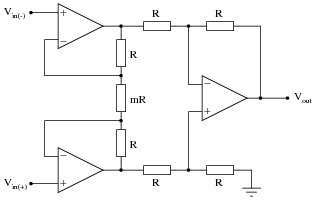
There is an equation describing the differential gain of an instrumentation amplifier, but it is easy enough to research so I’ll leave that detail up to you. What I’d like you to do here is algebraically derive that equation based on what you know of inverting and non-inverting operational amplifier circuits.
Suppose we apply 1 volt to the non-inverting input and ground the inverting input, giving a differential input voltage of 1 volt. Whatever voltage appears at the output of the instrumentation amplifier circuit, then, directly represents the voltage gain:

A hint for constructing an algebraic explanation for the circuit’s output voltage is to view the two “buffer” opamps separately, as inverting and non-inverting amplifiers:
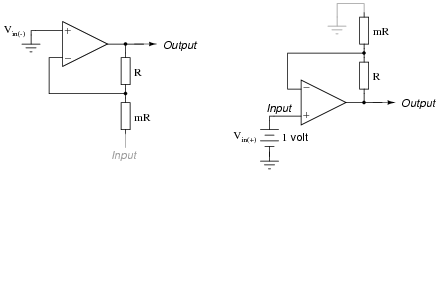
Note which configuration (inverting or non-inverting) each of these circuits resemble, develop transfer functions for each (Output = … Input), then combine the two equations in a manner representing what the subtractor circuit will do. Your final result should be the gain equation for an instrumentation amplifier in terms of m.
Reveal answerI won’t show you the complete answer, but here’s a start:
Equation for inverting side:
Output = − ( R mR) Input Equation for non-inverting side:
Output = ( R mR1 ) Input Notes:This question actually originated from one of my students as he tried to figure out an algebraic explanation for the instrumentation amplifier’s gain! I thought the idea was so good that I decided to include it as a question in the Socratic Electronics project.
Astute students will note that the negative sign in the inverting amplifier equation becomes very important in this proof. As an instructor, I often avoid signs, choosing to figure out the polarity of the signal as a final step after all the other arithmetic has been completed for a circuit analysis. As such, I usually present the inverting amplifier equation as [(Rf)/(Rin)] with the caveat of inverted polarity from input to output. Here, though, the negative sign becomes a vital part of the solution!