Facebook
 Google
 GitHub
 Linkedin
Digital Circuits
Switched Capacitor Circuitry
15 questions By Tony R. Kuphaldt
-
Question 4 of 15
Describe what happens to Vout (the voltage across capacitor C4) as time goes on, assuming the relay is continuously toggled by the oscillator circuit at a high frequency. Assume that the input voltage (Vin) is constant over time:
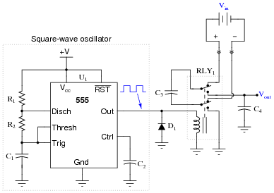
This type of circuit is often referred to as a flying capacitor circuit, with C3 being the “flying” capacitor. Explain why this is, and what possible benefit might be realized by using a flying capacitor circuit to sample a voltage.
Reveal answerFlying capacitor circuits are used to provide galvanic isolation between a sampled voltage source and voltage measurement circuitry.
Notes:I once worked for a company where thousands of these “flying capacitor” circuits were used to sample voltage across numerous series-connected electrochemical reduction cells, whose common-mode voltage could easily exceed 500 volts DC! This primitive technology provided isolation so that the data acquisition circuitry did not have to deal with that high common-mode voltage.
Incidentally, the relays we used were hermetically sealed, mercury-wetted contact, reed relays. These relays had a surprisingly long life, often several years! They were cycled at around 20 Hz, for several cycles, about once every minute (24 hours per day, 365 days per year).
-
Question 5 of 15
Suppose an engineer decided to use a flying capacitor circuit to sample voltage across a shunt resistor, to measure AC current from an electrical generator:
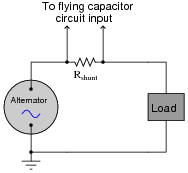
The frequency of the alternator’s output is 50 Hz. How does this affect the design of the flying capacitor circuit, so we ensure a fairly accurate reproduction of the AC signal at the output of the flying capacitor circuit? Generalize your answer to cover all conditions where the input signal varies over time.
Reveal answerThe switching frequency of the flying capacitor circuit must exceed the output frequency of the alternator by a substantial margin, or else the signal shape will not be faithfully reproduced at the circuit’s output.
Challenge question: if you were the technician or engineer on this project, what switching frequency would you suggest for the flying capacitor circuit? How would this criterion affect the design of the flying capacitor circuit itself (capacitor values, relay versus transistor switches)?
Notes:Ask your students to sketch an approximation of the flying capacitor circuit’s output waveform for different sampling frequencies. This question is a great lead-in to a discussion on Nyquist frequency, if your students are ready for it!
An important aspect of this question is for students to generalize from this specific circuit example to all systems where signals are sampled along discrete time intervals. In modern electronic circuitry, especially data acquisition circuitry, sample time can be a significant issue. In my experience, it is one of the primary reasons for digital systems giving poor results.
-
Question 6 of 15
In this circuit, a capacitor is alternately connected to a voltage source, then a load, by means of two MOSFET transistors that are never conducting at the same time:
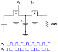
Note: the φ1 and φ2 pulse signals are collectively referred to as a non-overlapping, two-phase clock.
Consider the average amount of current through the load resistor, as a function of clock frequency. Assume that the “on” resistance of each MOSFET is negligible, so that the time required for the capacitor to charge is also negligible. As the clock frequency is increased, does the load resistor receive more or less average current over a span of several clock cycles? Here is another way to think about it: as the clock frequency increases, does the load resistor dissipate more or less power?
Now suppose we have a simple two-resistor circuit, where a potentiometer (connected as a variable resistor) throttles electrical current to a load:

It should be obvious in this circuit that the load current decreases as variable resistance R increases. What might not be so obvious is that the aforementioned switched capacitor circuit emulates the variable resistor R in the second circuit, so that there is a mathematical equivalence between f and C in the first circuit, and R in the second circuit, so far as average current is concerned. To put this in simpler terms, the switched capacitor network behaves sort of like a variable resistor.
Calculus is required to prove this mathematical equivalence, but only a qualitative understanding of the two circuits is necessary to choose the correct equivalency from the following equations. Which one properly describes the equivalence of the switched capacitor network in the first circuit to the variable resistor in the second circuit?
R = f CR = C fR = 1 fCR = fC Be sure to explain the reasoning behind your choice of equations.
Reveal answerAverage load current increases as clock frequency increases: R = \(\frac{1}{fC}\)
Notes:Perhaps the most important aspect of this question is students’ analytical reasoning: how did they analyze the two circuits to arrive at their answers? Be sure to devote adequate class time to a discussion of this, helping the weaker students grasp the concept of switched-capacitor/resistor equivalency by allowing stronger students to present their arguments.