Facebook
 Google
 GitHub
 Linkedin
Digital Circuits
Switched Capacitor Circuitry
15 questions By Tony R. Kuphaldt
-
Question 7 of 15
In this circuit, a capacitor is alternately connected in series between a voltage source and a load, then shorted, by means of two MOSFET transistors that are never conducting at the same time:
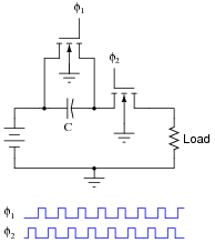
Note: the φ1 and φ2 pulse signals are collectively referred to as a non-overlapping, two-phase clock.
Consider the average amount of current through the load resistor, as a function of clock frequency. Assume that the “on” resistance of each MOSFET is negligible, so that the time required for the capacitor to charge is also negligible. As the clock frequency is increased, does the load resistor receive more or less average current over a span of several clock cycles? Here is another way to think about it: as the clock frequency increases, does the load resistor dissipate more or less power?
Now suppose we have a simple two-resistor circuit, where a potentiometer (connected as a variable resistor) throttles electrical current to a load:

It should be obvious in this circuit that the load current decreases as variable resistance R increases. What might not be so obvious is that the aforementioned switched capacitor circuit emulates the variable resistor R in the second circuit, so that there is a mathematical equivalence between f and C in the first circuit, and R in the second circuit, so far as average current is concerned. To put this in simpler terms, the switched capacitor network behaves sort of like a variable resistor.
Calculus is required to prove this mathematical equivalence, but only a qualitative understanding of the two circuits is necessary to choose the correct equivalency from the following equations. Which one properly describes the equivalence of the switched capacitor network in the first circuit to the variable resistor in the second circuit?
R = f CR = C fR = 1 fCR = fC Be sure to explain the reasoning behind your choice of equations.
Reveal answerAverage load current increases as clock frequency increases: R =\(\frac{1}{fC}\)
Notes:Perhaps the most important aspect of this question is students’ analytical reasoning: how did they analyze the two circuits to arrive at their answers? Be sure to devote adequate class time to a discussion of this, helping the weaker students grasp the concept of switched-capacitor/resistor equivalency by allowing stronger students to present their arguments.
-
Question 8 of 15
Identify the polarity of voltage across the load resistor in the following switched capacitor circuit (called a transresistor circuit). Note: φ1 and φ2 are two-phase, non-overlapping clock signals, and the switches are just generic representations of transistors.
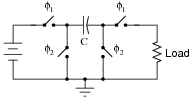
Identify the polarity of voltage across the load resistor in the following switched capacitor circuit. Note: the only difference between this circuit and the last is the switching sequence.

What difference would it make to the output signal of this operational amplifier circuit if the switching sequence of the switched capacitor network were changed? What difference would it make if the switching frequency were changed?

Reveal answer
The op-amp circuit will act as an inverting or non-inverting amplifier, depending on the switching sequence. Gain will be affected by switching frequency.
Challenge question: the second switched capacitor network is often referred to as a negative resistor equivalent. Explain why.
Notes:Some of the versatility of switched capacitor networks can be seen in these two circuit examples. Really, they’re the same circuit, just operated differently. Discuss with your students how this versatility may be an advantage in circuit design.
-
Question 9 of 15
Research the resistance equivalence equations for each of these switched-capacitor networks (using N-channel MOSFETs as switches), describing the emulated resistance (R) as a function of switching frequency (f) and capacitance (C):
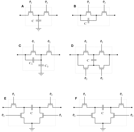
Note: φ1 and φ2 are two-phase, non-overlapping clock signals.
Reveal answerCircuit A: Parallel circuit \(R=\frac{1}{fC}\)
Circuit B: Series circuit \(R=\frac{1}{fC}\)
Circuit C: Series-parallel circuit \(R=\frac{1}{f(C1+C2)}\)
Circuit D: Bilinear circuit \(R=\frac{1}{4fC}\)
Circuit E: Negative transresistor circuit \(R=\frac{1}{fC}\) (the negative sign indicates polarity inversion)
Circuit F: Positive transresistor circuit \(R=\frac{1}{fC}\)
Notes:The mathematics required to derive these equations directly may be beyond your students’ ability, but they should still be able to research them! Some of the networks are directly equivalent to one another, making it easier for your students to associate equations: for instance, circuit F is equivalent to circuit B, and circuit E is the same thing as F except for the polarity inversion. It should not take a great deal of analysis to realize that circuits A and B must have the same equation as well.