
 Facebook
 Google
 GitHub
 Linkedin
Network Analysis Techniques
Thevenin’s, Norton’s, and Maximum Power Transfer Theorems
46 questions By Tony R. Kuphaldt
-
Question 37 of 46
Convert the following Norton equivalent circuit into a Thévenin equivalent circuit:

Reveal answer
Notes:Nothing special here, just practice converting between Thevenin and Norton sources. Be sure to ask your students to explain all their steps and reasoning in arriving at the answer.
-
Question 38 of 46
An ideal (perfect) current source is an abstraction with no accurate realization in life. However, we may approximate the behavior of an ideal current source with a high-voltage source and large series resistance:

Such a Thevenin equivalent circuit, however imperfect, will maintain a fairly constant current through a wide range of load resistance values.
Similarly, an ideal (perfect) voltage source is an abstraction with no accurate realization in life. Thankfully, though, it is not difficult to build voltage sources that are relatively close to perfect: circuits with very low internal resistance such that the output voltage sags only a little under high-current conditions.
But suppose we lived in a world where things were the opposite: where close-to-ideal current sources were simpler and more plentiful than close-to-ideal voltage sources. Draw a Norton equivalent circuit showing how to approximate an ideal voltage source using an ideal (perfect) current source and a shunt resistance.
Reveal answer
Notes:This question is not so much a practical one as it is designed to get students to think a little deeper about the differences between ideal voltage and current sources. In other words, it focuses on concepts rather than application.
-
Question 39 of 46
One day an electronics student decides to build her own variable-voltage power source using a 6-volt battery and a 10 kΩ potentiometer:
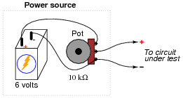
She tests her circuit by connecting a voltmeter to the output terminals and verifying that the voltage does indeed increase and decrease as the potentiometer knob is turned.
Later that day, her instructor assigns a quick lab exercise: measure the current through a parallel resistor circuit with an applied voltage of 3 volts, as shown in the following schematic diagram.

Calculating current in this circuit is a trivial exercise, she thinks to herself: 3 V ÷ 500 Ω = 6 mA. This will be a great opportunity to use the new power source circuit, as 3 volts is well within the voltage adjustment range!
She first sets up her circuit to output 3 volts precisely (turning the 10 kΩ potentiometer to the 50% position), measuring with her voltmeter as she did when initially testing the circuit. Then she connects the output leads to the two parallel resistors through her multimeter (configured as an ammeter), like this:
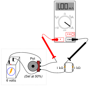
However, when she reads her ammeter display, the current only measures 1 mA, not 6 mA as she predicted. This is a very large discrepancy between her prediction and the measured value for current!
Use Thévenin’s Theorem to explain what went wrong in this experiment. Why didn’t her circuit behave as she predicted it would?
Reveal answerWith the 10 kΩ potentiometer set in the 50% position, this student’s power source circuit resembles a 3 volt source in series with a 5 kΩ resistance (the Thévenin equivalent circuit) rather than an ideal 3 volt source as assumed when she made her prediction for circuit current.
Follow-up question #1: explain what this student would have to do to use her adjustable-voltage power source circuit to properly demonstrate the lab circuit as assigned.
Follow-up question #2: identify at least one circuit failure which would result in zero measured (ammeter) current.
Notes:This challenges students to apply Thévenin’s Theorem to a practical scenario: a loaded voltage divider. Be sure to ask your students to show what the Thévenin equivalent circuit for the student’s power source is (set at 50%, or 3 volts output unloaded), and how they arrived at that equivalent circuit.





I think there is an error in 8th question, Thevenin’s resistance must be 479.53 and not 210.53
There is another mistake in question 39:
“this student’s power source circuit resembles a 3 volt source in series with a 5 kΩ resistance”—should be 2.5 kΩ resistance