
 Facebook
 Google
 GitHub
 Linkedin
Network Analysis Techniques
Thevenin’s, Norton’s, and Maximum Power Transfer Theorems
46 questions By Tony R. Kuphaldt
-
Question 40 of 46
Observe the following circuit:

Note that it is not reducible to a single resistance and power source. In other words, it is not a series-parallel combination circuit. And, while it is a bridge circuit, you are not able to simply analyze the resistor ratios because it is obviously not in a state of balance!
If you were asked to calculate voltage or current for any component in this circuit, it would be a difficult task . . . unless you know either Thévenin’s or Norton’s theorems, that is! Apply either one of these theorems to the determination of voltage across the 2.2 kΩ resistor.
Hint: consider the 2.2 kΩ resistor as the load in a Thévenin or Norton equivalent circuit.
Reveal answerV2.2kΩ = 5.6624 volts
Hint: the Thévenin equivalent circuit looks like this (with the 2.2 kΩ resistor connected as the load):

Notes:Both Thévenin’s and Norton’s theorems are powerful circuit analysis tools, if you know how to apply them! Students often have difficulty seeing how to analyze the bridge circuit (with the “load” resistor removed), using series-parallel and redrawing techniques. Be prepared to help them through this step during discussion time.
-
Question 41 of 46
Plot the power dissipation of the load resistance, for several values between 1 kΩ and 20 kΩ:
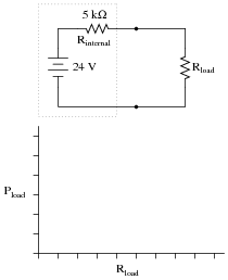
At what load resistance value is the load’s power dissipation maximized?
Reveal answer
Notes:What practical application can you think of for this principle of power maximization? In what applications might we be interested in delivering the maximum amount of power possible to a load?
-
Question 42 of 46
Explain what the Maximum Power Transfer Theorem is, in your own words.
Reveal answerThis I leave to you to research!
Notes:This theorem is very easy to research, being described in just about every introductory electronics textbook. While it may not be intuitive, at least it is useful and easy to remember!





I think there is an error in 8th question, Thevenin’s resistance must be 479.53 and not 210.53
There is another mistake in question 39:
“this student’s power source circuit resembles a 3 volt source in series with a 5 kΩ resistance”—should be 2.5 kΩ resistance