
 Facebook
 Google
 GitHub
 Linkedin
Network Analysis Techniques
Thevenin’s, Norton’s, and Maximum Power Transfer Theorems
46 questions By Tony R. Kuphaldt
-
Question 7 of 46
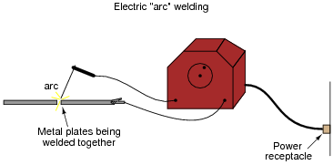
An electric arc welder is a low-voltage, high-current power source designed to supply enough electric current to sustain an arc capable of welding metal with its high temperature:
It is possible to derive a Norton equivalent circuit for an arc welder based on empirical measurements of voltage and current. Take for example these measurements, under loaded and no-load conditions:
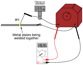
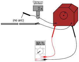
Based on these measurements, draw a Norton equivalent circuit for the arc welder.
Reveal answer
Notes:This practical scenario shows how Norton’s theorem may be used to “model” a complex device as two simple components (current source and resistor). Of course, we must make certain assumptions when modeling in this fashion: we assume, for instance, that the arc welder is a linear device, which may or may not be true.
Incidentally, there is such a thing as a DC-measuring clamp-on ammeter as shown in the illustrations, in case any one of your students ask. AC clamp-on meters are simpler, cheaper, and thus more popularly known, but devices using the Hall effect are capable of inferring DC current by the strength of an unchanging magnetic field, and these Hall-effect devices are available at modest expense.
-
Question 8 of 46
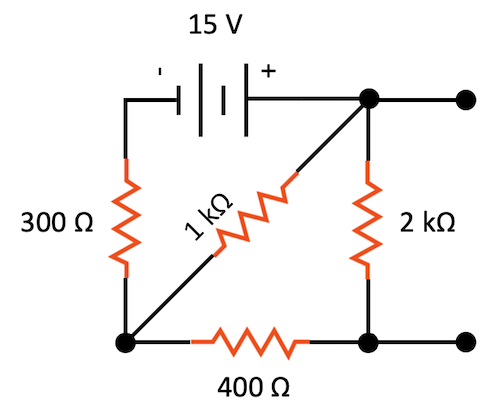
Convert this resistive network to its Thevenin equivalent:
Reveal answer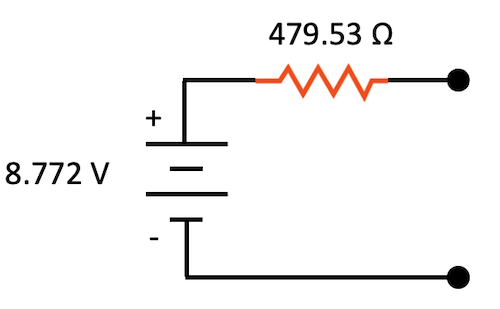
Thevenin equivalent circuit
Notes:Nothing but practice here. Have your students demonstrate how they did the Thévenin conversion, step-by-step.
-
Question 9 of 46
Resistive voltage dividers are very useful and popular circuits. However, it should be realized that their output voltages ßag” under load:
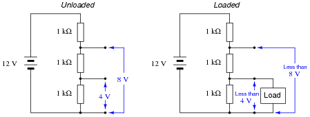
Just how much a voltage divider’s output will sag under a given load may be a very important question in some applications. Take for instance the following application where we are using a resistive voltage divider to supply an engine sensor with reduced voltage (8 volts) from the 12 volt battery potential in the automobile:
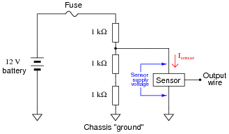
If the sensor draws no current (Isensor = 0 mA), then the voltage across the sensor supply terminals will be 8 volts. However, if we were asked to predict the voltage across the sensor supply terminals for a variety of different sensor current conditions, we would be faced with a much more complex problem:
Sensor current (Isensor) Sensor supply voltage
0 mA 8 volts
1 mA
2 mA
3 mA
4 mA
5 mA
One technique we could use to simplify this problem is to reduce the voltage divider resistor network into a Thévenin equivalent circuit. With the three-resistor divider reduced to a single resistor in series with an equivalent voltage source, the calculations for sensor supply voltage become much simpler.Show how this could be done, then complete the table of sensor supply voltages shown above.
Reveal answer
Sensor current (Isensor) Sensor supply voltage
0 mA 8 volts
1 mA 7.333 volts
2 mA 6.667 volts
3 mA 6 volts
4 mA 5.333 volts
5 mA 4.667 volts
Follow-up question: if we cannot allow the sensor supply voltage to fall below 6.5 volts, what is the maximum amount of current it may draw from this voltage divider circuit?Challenge question: figure out how to solve for these same voltage figures without reducing the voltage divider circuit to a Thévenin equivalent.
Notes:Students are known to ask, “When are we ever going to use Thévenin’s Theorem?” as this concept is introduced in their electronics coursework. This is a valid question, and should be answered with immediate, practical examples. This question does exactly that: demonstrate how to predict voltage “sag” for a loaded voltage divider in such a way that is much easier than using Ohm’s Law and Kirchhoff’s Laws directly.
Note the usage of European schematic symbols in this question. Nothing significant about this choice - just an opportunity for students to see other ways of drawing schematics.
Note also how this question makes use of ground symbols, but in a way where the concept is introduced gently: the first (example) schematics do not use ground symbols, whereas the practical (automotive) circuit does.






I think there is an error in 8th question, Thevenin’s resistance must be 479.53 and not 210.53
There is another mistake in question 39:
“this student’s power source circuit resembles a 3 volt source in series with a 5 kΩ resistance”—should be 2.5 kΩ resistance