
 Facebook
 Google
 GitHub
 Linkedin
Network Analysis Techniques
Thevenin’s, Norton’s, and Maximum Power Transfer Theorems
46 questions By Tony R. Kuphaldt
-
Question 4 of 46
Sometimes you will see amplifier circuits expressed as collections of impedances and dependent sources:
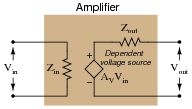
With this model, the amplifier appears as a load (Zin) to whatever signal source its input is connected to, boosts that input voltage by the gain factor (AV), then outputs the boosted signal through a series output impedance (Zout) to whatever load is connected to the output terminals:
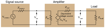
Explain why all these impedances (shown as resistors) are significant to us as we seek to apply amplifier circuits to practical applications. Which of these impedances do you suppose are typically easier for us to change, if they require changing at all?
Reveal answerZin should equal Zsource and Zload should equal Zout for maximum power transfer from source to load. Typically, the values of Zsource and Zload are fixed by the nature of the source and load devices, respectively, and the only impedances we have the freedom to alter are those within the amplifier.
Notes:This question has multiple purposes: to introduce students to the modeling concept of a dependent source, to show how an amplifier circuit may be modeled using such a dependent source, and to probe into the importance of impedances in a complete amplification system: source, amplifier, and load. Many interesting things to discuss here!
-
Question 5 of 46
The voltage divider network employed to create a DC bias voltage for many transistor amplifier circuits has its own effect on amplifier input impedance. Without considering the presence of the transistor or the emitter resistance, calculate the impedance as “seen” from the input terminal resulting from the two resistors R1 and R2 in the following common-collector amplifier circuit:
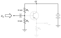
Remember, what you are doing here is actually determining the Thévenin/Norton equivalent resistance as seen from the input terminal by an AC signal. The input coupling capacitor reactance is generally small enough to be safely ignored.
Next, calculate the input impedance of the same circuit, this time considering the presence of the transistor and emitter resistor, assuming a current gain (β or hfe) of 60, and the following formula for impedance at the base resulting from β and RE:
$$Z_B \approx (\beta + 1) R_E$$

Develop an equation from the steps you take in calculating this impedance value.
Reveal answerZin (without considering transistor) = 7.959 kΩ
Zin (complete circuit) ≈ 7.514 kΩ
$$Z_{in} \approx \frac{1}{\frac{1}{R_1}+\frac{1}{R_2}+\frac{1}{(\beta+1) R_E}}$$
Notes:This question is primarily an exercise in applying Thévenin’s theorem to the amplifier circuit. The most confusing point of this for most students seems to be how to regard the DC power supply. A review of Thévenin equivalent circuit procedures and calculations might be in order here.
To be proper, the transistor’s dynamic emitter resistance (r′e) could also be included in this calculation, but this just makes things more complex. For this question, I wanted to keep things as simple as possible by just having students concentrate on the issue of integrating the voltage divider impedance with the transistor’s base impedance. With an emitter resistor value of 1500 ohms, the dynamic emitter resistance is negligibly small anyway.
-
Question 6 of 46
Determining the output impedance of a common-emitter amplifier is impossible unless we know how to model the transistor in terms of components whose behavior is simple to express.
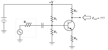
When in its active mode, a transistor operates like a current regulator. This is similar enough to the behavior of a current source that we may use a source to model the transistor’s behavior for the sake of this impedance determination:
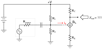
Now, apply the same steps you would use in determining the Thévenin or Norton equivalent impedance to the output of this amplifier circuit, and this will yield the amplifier’s output impedance. Draw an equivalent circuit for the amplifier during this Thévenizing/Nortonizing process to show how the output impedance is determined.
Reveal answer
I’m leaving it up to you to explain why the amplifier circuit reduces to something as simple as this!
Follow-up question: what is the significance of showing the transistor as a current source using a diamond-shaped symbol rather than a circle? You should be familiar by now with circular current source symbols, but what does a diamond-shaped current source symbol specifically represent in a schematic diagram?
Notes:The main problem students usually have when Thévenizing or Nortonizing this circuit is what to do with the current source. They may remember that voltage sources become shorted during the impedance-determination process, but usually make the mistake of doing the exact same thing with current sources. Remind your students if necessary that each source is to be replaced by its respective internal impedance. For voltage sources (with zero internal impedance, ideally) it means replacing them with short circuits. For current sources (with infinite internal impedance, ideally) it means replacing them with open circuits.



I think there is an error in 8th question, Thevenin’s resistance must be 479.53 and not 210.53
There is another mistake in question 39:
“this student’s power source circuit resembles a 3 volt source in series with a 5 kΩ resistance”—should be 2.5 kΩ resistance