
 Facebook
 Google
 GitHub
 Linkedin
Network Analysis Techniques
Thevenin’s, Norton’s, and Maximum Power Transfer Theorems
46 questions By Tony R. Kuphaldt
-
Question 28 of 46
Suppose you were handed a black box with two metal terminals on one side, for attaching electrical (wire) connections. Inside this box, you were told, was a voltage source connected in series with a resistance.

Your task was to experimentally determine the values of the voltage source and the resistor inside the box, and you did just that. From your experimental data you then sketched a circuit with the following component values:
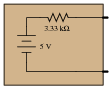
However, you later discovered that you had been tricked. Instead of containing a single voltage source and a single resistance, the circuit inside the box actually looked like this:
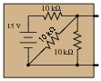
Demonstrate that these two different circuits are indistinguishable from the perspective of the two metal terminals, and explain what general principle this equivalence represents.
Reveal answerA good way to demonstrate the electrical equivalence of these circuits is to calculate their responses to identical load resistor values. The equivalence you see here is an application of Thévenin’s Theorem.
Notes:Ask your students to clearly state Thévenin’s Theorem, and explain how it may be applied to the two-resistor circuit to obtain the one-resistor circuit.
-
Question 29 of 46
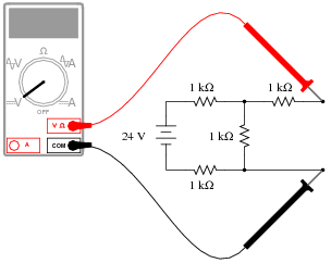
Examine this circuit, consisting of an ideal voltage source and several resistors:

First, calculate the voltage seen at the load terminals with a voltmeter directly connected across them (an open-circuit condition):
Next, calculate the current seen at the load terminals with an ammeter directly connected across them (a short-circuit condition):
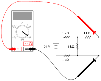
Based on these open- and short-circuit calculations, draw a new circuit consisting of a single voltage source and a single (series) resistor that will respond in the exact same manner. In other words, design an equivalent circuit for the circuit shown here, using the minimum number of possible components.
Reveal answer
Follow-up question: is this circuit truly equivalent to the original shown in the question? Sure, it responds the same under extreme conditions (open-circuit and short-circuit), but will it respond the same as the original circuit under modest load conditions (say, with a 5 kΩ resistor connected across the load terminals)?
Notes:The purpose of this question is to get students thinking about Thévenin equivalent circuits from the perspective of how the original circuit responds to extreme variations in load resistance.
This question is also a good review of voltmeter and ammeter behavior: that ideal voltmeters act as open circuits (infinite input resistance) while ideal ammeters act as short circuits (zero input impedance).
-
Question 30 of 46
An electric arc welder is a low-voltage, high-current power source used to generate hot arcs capable of melting metal. Note the voltage and current measurements taken for this particular welder:
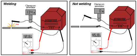
Determine two Thévenin equivalent circuits for the arc welder. The first circuit will simply be an AC voltage source and an internal impedance. The second circuit will be a voltage source and internal impedance connected through an ideal transformer with a step-down ratio of 8 to 1:
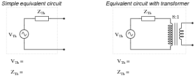
Reveal answerSimple equivalent circuit
VTh = 45.8 volts
ZTh = 0.2478 Ω
Equivalent circuit with transformer
VTh = 366.4 volts
ZTh = 15.86 Ω
Notes:This practical scenario shows how Thévenin’s theorem may be used to “model” a complex device as two simple components (voltage source and resistor). Of course, we must make certain assumptions when modeling in this fashion: we assume, for instance, that the arc welder is a linear device, which may or may not be true.







I think there is an error in 8th question, Thevenin’s resistance must be 479.53 and not 210.53
There is another mistake in question 39:
“this student’s power source circuit resembles a 3 volt source in series with a 5 kΩ resistance”—should be 2.5 kΩ resistance