
 Facebook
 Google
 GitHub
 Linkedin
Network Analysis Techniques
Thevenin’s, Norton’s, and Maximum Power Transfer Theorems
46 questions By Tony R. Kuphaldt
-
Question 13 of 46
A very common sort of graph used in electronics work is the load line, showing all possibilities of load voltage and load current that a particular power source is able to supply to a load:
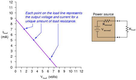
Note how the load line shows the voltage “sag” of the power source in relation to the amount of current drawn by the load. At high currents, the output voltage will be very low (upper-left end of load line). At low currents, the output voltage will be near its maximum (lower-right end of load line). If all internal components of the power source are linear in nature, the load line will always be perfectly straight.
Plot the load line for a power source having an internal voltage (Vinternal) of 11 volts and an internal resistance (Rinternal) of 1.2 kΩ. Superimpose your load line onto the load line graph shown above. Hint: it only takes two points to define a line!
Reveal answer
Hint: the easiest points on find on this load line are the points representing open-circuit and short-circuit conditions (i.e. Rload = ∞ Ω and Rload = 0 Ω, respectively).
Follow-up questions: what will happen to the load line if we change the internal resistance of the power source circuit? What will happen to the load line if we change the internal voltage value of the power source circuit?
Notes:The purpose of this question is to lend an analytical geometric perspective to the subject of power source behavior, by showing how the output voltage and current may be plotted on a graph. The condition of circuit linearity is important, as it permits us to confidently plot the load line by finding only two points on it.
-
Question 14 of 46
Give a step-by-step procedure for reducing this circuit to a Norton equivalent circuit (one current source in parallel with one resistor):

Reveal answerI will let you research the procedure for determining Norton equivalent circuits, and explain it in your own words. Here is the equivalent circuit for the circuit given in the question:

Notes:It should be easy for your students to research an algorithm (step-by-step procedure) for determining a Norton equivalent circuit. Let them do the work, and explain it to you and their classmates!
-
Question 15 of 46
Suppose you had an AC/DC power supply, which performed as follows (open-circuit and loaded test conditions):
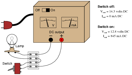
Draw a Thévenin equivalent circuit to model the behavior of this power supply.
Reveal answer
Follow-up question: is the switch shown in the on or off position, in the pictorial diagram?
Notes:Discuss with your students how Thévenin’s theorem allows us to model fairly complex power-supply circuits as simply a voltage source and series resistance (at least approximately). Discuss also the limitations of this modeling, especially in light of the condition of linearity for the proper application of Thévenin’s theorem.







I think there is an error in 8th question, Thevenin’s resistance must be 479.53 and not 210.53
There is another mistake in question 39:
“this student’s power source circuit resembles a 3 volt source in series with a 5 kΩ resistance”—should be 2.5 kΩ resistance