
 Facebook
 Google
 GitHub
 Linkedin
Network Analysis Techniques
Thevenin’s, Norton’s, and Maximum Power Transfer Theorems
46 questions By Tony R. Kuphaldt
-
Question 10 of 46
Give a step-by-step procedure for “Thévenizing” any circuit: finding the Thévenin equivalent voltage (VThevenin) and Thévenin equivalent resistance (RThevenin).
- Step #1:
- Step #2:
Reveal answerThis is easy enough for you to look up in any electronics textbook. I’ll leave you to it!
Follow-up question: describe the difference in how one must consider voltage sources versus current sources when calculating the equivalent circuit’s resistance (RThevenin) of a complex circuit containing both types of sources?
Notes:I really mean what I say here about looking this up in a textbook. Thévenin’s Theorem is a very well-covered subject in many books, and so it is perfectly reasonable to expect students will do this research on their own and come back to class with a complete answer.
The follow-up question is very important, because some circuits (especially transistor amplifier circuits) contain both types of sources. Knowing how to consider each one in the process of calculating the Thévenin equivalent resistance for a circuit is very important. When performing this analysis on transistor amplifiers, the circuit often becomes much simpler than its original form with all the voltage sources shorted and current sources opened!
-
Question 11 of 46
A voltage source is a source of electricity that (ideally) outputs a constant voltage. That is, a perfect voltage source will hold its output voltage constant regardless of the load imposed upon it:
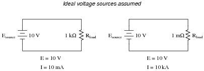
In real life, there is no such thing as a perfect voltage source, but sources having extremely low internal resistance come close.
Another type of electricity source is the current source, which (ideally) outputs a constant current regardless of the load imposed upon it. A common symbol for a current source is a circle with an arrow inside (always pointing in the direction of conventional flow, not electron flow!). Another symbol is two intersecting circles, with an arrow nearby pointing in the direction of conventional flow:
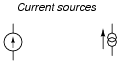
Predict how an ideal current source would behave for the following two load scenarios:
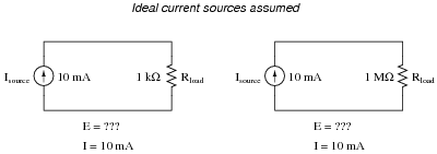
Reveal answer
Follow-up question: identify the polarity of the voltage drops across the resistors in the circuits shown above.
Notes:Let students know that there really is such a thing as a perfect current source, just as there is no such thing as a perfect voltage source. However, there are devices the closely approximate ideal current sources (current transformers in AC circuits and “current mirror” DC transistor circuits, for example).
-
Question 12 of 46
Ideal voltage sources and ideal current sources, while both being sources of electrical power, behave very differently from one another:
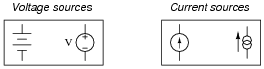
Explain how each type of electrical source would behave if connected to a variable-resistance load. As this variable resistance were increased and decreased, how would each type of source respond?
Reveal answerAn ideal voltage source will output as much or as little current as necessary to maintain a constant voltage across its output terminals, for any given load resistance. An ideal current source will output as much or as little voltage as necessary to maintain a constant current through it, for any given load resistance.
Notes:Ask your students to think of a few “thought experiment” scenarios where voltage and current sources could be put to test. Have them invent voltage and current values for these voltage and current sources, respectively, then calculate all other circuit parameters given several different values of load resistance.





I think there is an error in 8th question, Thevenin’s resistance must be 479.53 and not 210.53
There is another mistake in question 39:
“this student’s power source circuit resembles a 3 volt source in series with a 5 kΩ resistance”—should be 2.5 kΩ resistance