
 Facebook
 Google
 GitHub
 Linkedin
DC Electric Circuits
Time Constant Calculations
52 questions By Tony R. Kuphaldt
-
Question 43 of 52
Determine the amount of time needed for the capacitor voltage (VC) to fall to the specified levels after the switch is thrown to the “discharge” position, assuming it had first been charged to full battery voltage:

VC Time
10 volts
8 volts
6 volts
4 volts
2 volts
Trace the direction of electron flow in the circuit, and also mark all voltage polarities.Reveal answer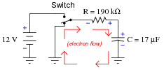
VC Time
10 volts 588.9 ms
8 volts 1.31 s
6 volts 2.24 s
4 volts 3.55 s
2 volts 5.79 s
Notes:Ask your students to explain how they set up each calculation.
-
Question 44 of 52
A submarine sonar system uses a “bank” of parallel-connected capacitors to store the electrical energy needed to send brief, powerful pulses of current to a transducer (a “speaker” of sorts). This generates powerful sound waves in the water, which are then used for echo-location. The capacitor bank relieves the electrical generators and power distribution wiring aboard the submarine from having to be rated for huge surge currents. The generator trickle-charges the capacitor bank, and then the capacitor bank quickly dumps its store of energy to the transducer when needed:
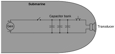
As you might well imagine, such a capacitor bank can be lethal, as the voltages involved are quite high and the surge current capacity is enormous. Even when the DC generator is disconnected (using the “toggle” disconnect switch shown in the schematic), the capacitors may hold their lethal charge for many days.
To help decreases the safety risk for technical personnel working on this system, a “discharge” switch is connected in parallel with the capacitor bank to automatically provide a path for discharge current whenever the generator disconnect switch is opened:

Suppose the capacitor bank consists of forty 1500 μF capacitors connected in parallel (I know the schematic only shows three, but . . .), and the discharge resistor is 10 kΩ in size. Calculate the amount of time it takes for the capacitor bank to discharge to 10 percent of its original voltage and the amount of time it takes to discharge to 1 percent of its original voltage once the disconnect switch opens and the discharge switch closes.
Reveal answerTime to reach 10% ≈ 23 minutes
Time to reach 1% ≈ 46 minutes
Follow-up question: without using the time constant formula again, calculate how long it will take to discharge to 0.1% of its original voltage. How about 0.01%?
Notes:The follow-up question illustrates an important mathematical principle regarding logarithmic decay functions: for every passing of a fixed time interval, the system decays by the same factor. This is most clearly (and popularly) seen in the concept of half-life for radioactive substances, but it is also seen here for RC (or LR) circuits.
-
Question 45 of 52
The model “555” integrated circuit is a very popular and useful “chip” used for timing purposes in electronic circuits. The basis for this circuit’s timing function is a resistor-capacitor (RC) network:

In this configuration, the “555” chip acts as an oscillator: switching back and forth between “high” (full voltage) and “low” (no voltage) output states. The time duration of one of these states is set by the charging action of the capacitor, through both resistors (R1 and R2 in series). The other state’s time duration is set by the capacitor discharging through one resistor (R2):
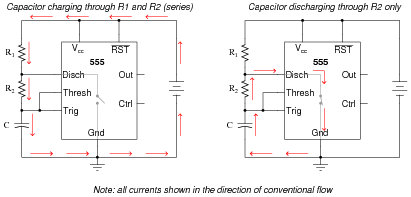
Obviously, the charging time constant must be τcharge = (R1 R2)C, while the discharging time constant is τdischarge = R2C. In each of the states, the capacitor is either charging or discharging 50% of the way between its starting and final values (by virtue of how the 555 chip operates), so we know the expression e[(−t)/(τ)] = 0.5, or 50 percent.
Develop two equations for predicting the “charge” time and “discharge” time of this 555 timer circuit, so that anyone designing such a circuit for specific time delays will know what resistor and capacitor values to use.
Footnotes:
For those who must know why, the 555 timer in this configuration is designed to keep the capacitor voltage cycling between 1/3 of the supply voltage and 2/3 of the supply voltage. So, when the capacitor is charging from 1/3VCC to its (final) value of full supply voltage (VCC), having this charge cycle interrupted at 2/3VCC by the 555 chip constitutes charging to the half-way point, since 2/3 of half-way between 1/3 and 1. When discharging, the capacitor starts at 2/3VCC and is interrupted at 1/3VCC, which again constitutes 50% of the way from where it started to where it was (ultimately) headed
.Reveal answertcharge = − ln0.5 (R1 R2)C tdischarge = − ln0.5 R2 C Notes:Although it may seem premature to introduce the 555 timer chip when students are just finishing their study of DC, I wanted to provide a practical application of RC circuits, and also of algebra in generating useful equations. If you deem this question too advanced for your student group, by all means skip it.
Incidentally, I simplified the diagram where I show the capacitor discharging: there is actually another current at work here. Since it wasn’t relevant to the problem, I omitted it. However, some students may be adept enough to catch the omission, so I show it here:
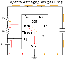
Note that this second current (through the battery) does not go anywhere near the capacitor, and so is irrelevant to the discharge cycle time.




Maybe this will help someone else. The general formulas for V(t) and I(t) in question 25 (and the x(t) versions in question s 23 and 14) contain typos (or maybe hypertext coding glitches). They should actually be V(t) = (Vf-Vo)(1-e^(-t/𝛕)) + Vo, I(t) = (If-Io)(1-e^(-t/𝛕)) + Io in question 25. Those are correct in the PDF download version. In questions 23 and 24 the equations are x = xinitial + ( xfinal − xinitial ) ( 1 − e[(−t)/(τ)] ).