Facebook
 Google
 GitHub
 Linkedin
Digital Circuits
Timer Circuits
18 questions By Tony R. Kuphaldt
-
Question 13 of 18
Pulse Width Modulation, or PWM, is a very popular means of controlling power to an electrical load such as a light bulb or a DC motor. With PWM control, the duty cycle of a high-frequency digital (on/off) signal is varied, with the effect of varying power dissipation at the load:

One of the major advantages to using PWM to proportion power to a load is that the final switching transistor operates with minimal heat dissipation. If we were to use a transistor in its linear (“active”) mode, it would dissipate far more heat when controlling the speed of this motor! By dissipating less heat, the circuit wastes less power.
Explain why the power transistor in this circuit runs cooler when buffering the PWM signal from the 555 timer, rather than if it were operated in linear mode. Also, identify which direction the potentiometer wiper must be moved to increase the speed of the motor.
Challenge question: suppose we needed to control the power of a DC motor, when the motor’s operating voltage was far in excess of the 555 timer’s operating voltage. Obviously, we need a separate power supply for the motor, but how would we safely interface the 555’s output with the power transistor to control the motor speed? Draw a schematic diagram to accompany your answer.
Reveal answerI’ll let you research the answer to why PWM is a more energy-efficient way to control load power. This is a very important concept in power electronics!
To increase the speed of the motor, move the potentiometer wiper up (as pictured in the schematic).
Here is one possible solution to the problem of interfacing a 555 timer to a high-voltage DC motor:

Notes:There is much literature available discussing PWM power control, and its advantages over linear power control. Your students should have no difficulty finding it on their own!
Discuss with them the proposed solution to the high-voltage motor problem. What purpose(s) do/does the solid-state relay serve? Is there a way to achieve PWM control over the motor without using an optocoupled device? If so, how? Let your students show their solutions and discuss the practicality of each.
-
Question 14 of 18
It is common to see a capacitor connected between the “Control” terminal and ground in 555 timer circuits, especially when precise timing is important.
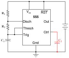
Explain what purpose the capacitor C2 serves in this circuit.
Reveal answerC2 acts as a decoupling capacitor, to help stabilize the threshold and trigger reference voltages internal to the 555.
Challenge question: what operational parameters of the circuit define the necessary capacitance value of C2?
Notes:Decoupling power supply pins on a chip is important, but here students get to see another variation of decoupling. If time permits, work through a sample problem with your students sizing capacitor C2, given a certain operating frequency of the astable circuit. Note: this will give you another opportunity to use Thévenin’s Theorem . . .
-
Question 15 of 18
Special integrated circuits called delay elements or delay gates are manufactured to provide nanoseconds’ worth of intentional time delays in digital circuits. Identify a part number for such an IC, research its datasheet, and describe an application where one might be needed.
Reveal answerOne part number for you to research is 74LS31. Such delay elements might be used to provide ample set-up and/or hold times for signals entering flip-flop.
Notes:Discuss with your students why such devices exist, in light of the existence of 555 timers. Why couldn’t a 555 timer be used for the same purpose as the 74LS31?
Related Tools:
- Step-up, Step-down, and Isolation Transformers
- Design Project: Simple Component Curve-Tracer Circuit