Facebook
 Google
 GitHub
 Linkedin
Digital Circuits
Timer Circuits
18 questions By Tony R. Kuphaldt
-
Question 10 of 18
What would happen to the operation of this astable 555 timer circuit if a resistor were accidently connected between the “Control” terminal and ground? Explain the reason for your answer.
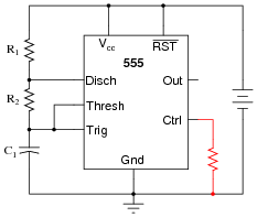
Reveal answerThe addition of a resistor between the Control terminal and ground would increase the frequency of the circuit, as well as decrease the peak-to-peak amplitude of the “sawtooth” wave signal across the timing capacitor.
Follow-up question: does the addition of this resistor affect the output signal (pin 3) amplitude as well? Explain why or why not. If it amplitude is affected, does it increase or decrease with the resistor in place?
Notes:Ask your students to explain why frequency and amplitude changes in this circuit. It is far too easy for a student to simply repeat the answer given by the worksheet! Hold your students accountable to reasoning through the operation of a circuit like this.
-
Question 11 of 18
A student builds their first astable 555 timer circuit, using a TLC555CP chip. Unfortunately, it seems to have a problem. Sometimes, the output of the timer simply stops oscillating, with no apparent cause. Stranger yet, the problem often occurs at the precise time anyone moves their hand within a few inches of the circuit board (without actually touching anything!).
What could the student have done wrong in assembling this circuit to cause such a problem? What steps would you take to troubleshoot this problem?
Reveal answerI won’t reveal the most probable cause, but I will give you this hint: the TLC555CP integrated circuit (“chip”) uses CMOS technology.
Notes:Every year it seems I have at least one student who experiences this particular problem, usually as a result of hasty circuit assembly (not making all necessary connections to pins on the chip). This is a good question to brainstorm with your class on, exploring possible causes and methods of diagnosis.
-
Question 12 of 18
Identify at least one component fault that would cause the final 555 timer output to always remain low:

For each of your proposed faults, explain why it will cause the described problem.
Reveal answer- Resistor R1 failed open.
- Solder bridge past resistor R2.
- No power to either 555 timer IC.
Notes:Be sure to discuss the reasons why each of your students’ proposed component faults would cause the final output to never go high. The possibilities range from the obvious to the obscure, and exploring them will strengthen your students’ understanding of the 555 as a monostable multivibrator.
Related Tools:
- Step-up, Step-down, and Isolation Transformers
- Design Project: Simple Component Curve-Tracer Circuit