Facebook
 Google
 GitHub
 Linkedin
Digital Circuits
Timer Circuits
18 questions By Tony R. Kuphaldt
-
Question 7 of 18
A sequential timer circuit may be constructed from multiple 555 timer ICs cascaded together. Examine this circuit and determine how it works:
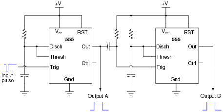
Can you think of any practical applications for a circuit such as this?
Reveal answerEach 555 timer’s cycle is triggered by the negative edge of the pulse on the trigger terminal. A passive differentiator network between each 555 timer ensures that only a brief negative-going pulse is sent to the trigger terminal of the next timer from the output terminal of the one before it.
Follow-up question: when timer circuits are cascaded like this, do their time delays add or multiply to make the total delay time? Be sure to explain your reasoning.
Notes:Practical applications abound for such a circuit. One whimsical application is to energize sequential tail-light bulbs for an automobile, to give an interesting turn-signal visual effect. A sequential timer circuit was used to do just this on certain years of (classic) Ford Cougar cars. Other, more utilitarian, applications for sequential timers include start-up sequences for a variety of electronic systems, traffic light controls, and automated household appliances.
-
Question 8 of 18
Predict how the operation of this astable 555 timer circuit will be affected as a result of the following faults. Specifically, identify what will happen to the capacitor voltage (VC1) and the output voltage (Vout) for each fault condition. Consider each fault independently (i.e. one at a time, no multiple faults):

- Resistor R1 fails open:
- Solder bridge (short) across resistor R1:
- Resistor R2 fails open:
- •Solder bridge (short) across resistor R2:
- Capacitor C1 fails shorted:
For each of these conditions, explain why the resulting effects will occur.
Reveal answer- Resistor R1 fails open: Capacitor voltage holds at last value, output voltage holds at last value.
- Solder bridge (short) across resistor R1: Timer IC will become damaged at the first discharge cycle.
- Resistor R2 fails open: Capacitor voltage holds at last value, output voltage holds at last value.
- Solder bridge (short) across resistor R2: Oscillation frequency nearly doubles, and the duty cycle increases to nearly 100%.
- Capacitor C1 fails shorted: Capacitor voltage goes to 0 volts DC, output voltage stays “high”.
Notes:The purpose of this question is to approach the domain of circuit troubleshooting from a perspective of knowing what the fault is, rather than only knowing what the symptoms are. Although this is not necessarily a realistic perspective, it helps students build the foundational knowledge necessary to diagnose a faulted circuit from empirical data. Questions such as this should be followed (eventually) by other questions asking students to identify likely faults based on measurements.
-
Question 9 of 18
This circuit uses a “555” integrated circuit to produce a low-frequency square-wave voltage signal (seen between the “Out” terminal of the chip and ground), which is used to turn a pair of transistors on and off to flash a large lamp. Predict how this circuit will be affected as a result of the following faults. Consider each fault independently (i.e. one at a time, no multiple faults):

- Transistor Q1 fails open (collector-to-emitter):
- Transistor Q2 fails open (collector-to-emitter):
- Resistor R3 fails open:
- Transistor Q1 fails shorted (collector-to-emitter):
For each of these conditions, explain why the resulting effects will occur.
Reveal answer- Transistor Q1 fails open (collector-to-emitter): Lamp remains off, no current through any terminal of Q2.
- Transistor Q2 fails open (collector-to-emitter): Lamp remains off, no current through any terminal of Q2, normal base current through Q1, no current through collector of Q1.
- Resistor R3 fails open: Lamp remains off, no current through any terminal of Q1 or Q2.
- Transistor Q1 fails shorted (collector-to-emitter): Lamp remains on, full “on” current levels through terminals of Q1 and Q2.
Notes:The purpose of this question is to approach the domain of circuit troubleshooting from a perspective of knowing what the fault is, rather than only knowing what the symptoms are. Although this is not necessarily a realistic perspective, it helps students build the foundational knowledge necessary to diagnose a faulted circuit from empirical data. Questions such as this should be followed (eventually) by other questions asking students to identify likely faults based on measurements.
Related Tools:
- Step-up, Step-down, and Isolation Transformers
- Design Project: Simple Component Curve-Tracer Circuit