Facebook
 Google
 GitHub
 Linkedin
Digital Circuits
High-Reliability Circuits
-
Question 1
Don’t just sit there! Build something!! Learning to analyze relay circuits requires much study and practice. Typically, students practice by working through lots of sample problems and checking their answers against those provided by the textbook or the instructor. While this is good, there is a much better way.
You will learn much more by actually building and analyzing real circuits, letting your test equipment provide the “answers” instead of a book or another person. For successful circuit-building exercises, follow these steps:
- Draw the schematic diagram for the relay circuit to be analyzed.
- Carefully build this circuit on a breadboard or other convenient medium.
- Check the accuracy of the circuit’s construction, following each wire to each connection point, and verifying these elements one-by-one on the diagram.
- Analyze the circuit, determining all logic states for given input conditions.
- Carefully measure those logic states, to verify the accuracy of your analysis.
- If there are any errors, carefully check your circuit’s construction against the diagram, then carefully re-analyze the circuit and re-measure.
Always be sure that the power supply voltage levels are within specification for the relay coils you plan to use. I recommend using PC-board relays with coil voltages suitable for single-battery power (6 volt is good). Relay coils draw quite a bit more current than, say, semiconductor logic gates, so use a “lantern” size 6 volt battery for adequate operating life.
One way you can save time and reduce the possibility of error is to begin with a very simple circuit and incrementally add components to increase its complexity after each analysis, rather than building a whole new circuit for each practice problem. Another time-saving technique is to re-use the same components in a variety of different circuit configurations. This way, you won’t have to measure any component’s value more than once.
Reveal answerLet the electrons themselves give you the answers to your own “practice problems”!
Notes:It has been my experience that students require much practice with circuit analysis to become proficient. To this end, instructors usually provide their students with lots of practice problems to work through, and provide answers for students to check their work against. While this approach makes students proficient in circuit theory, it fails to fully educate them.
Students don’t just need mathematical practice. They also need real, hands-on practice building circuits and using test equipment. So, I suggest the following alternative approach: students should build their own “practice problems” with real components, and try to predict the various logic states. This way, the relay theory “comes alive,” and students gain practical proficiency they wouldn’t gain merely by solving Boolean equations or simplifying Karnaugh maps.
Another reason for following this method of practice is to teach students scientific method: the process of testing a hypothesis (in this case, logic state predictions) by performing a real experiment. Students will also develop real troubleshooting skills as they occasionally make circuit construction errors.
Spend a few moments of time with your class to review some of the “rules” for building circuits before they begin. Discuss these issues with your students in the same Socratic manner you would normally discuss the worksheet questions, rather than simply telling them what they should and should not do. I never cease to be amazed at how poorly students grasp instructions when presented in a typical lecture (instructor monologue) format!
A note to those instructors who may complain about the “wasted” time required to have students build real circuits instead of just mathematically analyzing theoretical circuits:
What is the purpose of students taking your course?
If your students will be working with real circuits, then they should learn on real circuits whenever possible. If your goal is to educate theoretical physicists, then stick with abstract analysis, by all means! But most of us plan for our students to do something in the real world with the education we give them. The “wasted” time spent building real circuits will pay huge dividends when it comes time for them to apply their knowledge to practical problems.
Furthermore, having students build their own practice problems teaches them how to perform primary research, thus empowering them to continue their electrical/electronics education autonomously.
In most sciences, realistic experiments are much more difficult and expensive to set up than electrical circuits. Nuclear physics, biology, geology, and chemistry professors would just love to be able to have their students apply advanced mathematics to real experiments posing no safety hazard and costing less than a textbook. They can’t, but you can. Exploit the convenience inherent to your science, and get those students of yours practicing their math on lots of real circuits!
-
Question 2
The equation relating probability of continued performance for a component or a system versus time may be expressed as follows:
x = e−t / m Where,
x = Probability (a number between 0 and 1, inclusive)
e = Euler’s constant ( ≈ 2.7182818)
t = Time of continuous operation
m = Mean Time Between Failure of the component or system
The unit of time for both t and m must be the same. That is, if t is measured in years, then m must also be expressed in years or else the equation will give very misleading answers.
Suppose, though, we were given m in years, and the operating time t in days. Substitute the relationship td = 365 ty into the reliability equation so that we will have a new equation that can take t in days (td) and m in years, and still provide the correct answer.
Reveal answerx = e−td / 365 m Notes:This is really nothing more than a simple exercise in mathematical substitution.
The equation came from the Standard Handbook of Engineering Calculations by Tyler G Hicks, P.E. (1972), page 5-21.
-
Question 3
Explain what the following statement means, with regard to the design of electronic circuits:
- Faults are inevitable, but failure is not.
Specifically, what does this philosophy mean for your career as an electronics professional, entrusted with the installation, maintenance, and possibly design of complex systems?
Reveal answerComponents can and will fail, but the system as a whole does not have to be so fragile as to fail with a single component fault.
Notes:Discuss with your students the ramifications of the “fault, but no failure” philosophy with regard to their daily jobs. How do their actions impact the reliability of systems, and what can they do to minimize the chances of system failures?
-
Question 4
An important parameter of high-reliability systems is abbreviated MTBF. What does this acronym stand for?
Reveal answer“MTBF” = Mean Time Between Failures, a statistical figure based on the failure rate of a large batch of continuously operating units.
Notes:It is important for students to realize that an MTBF figure is not to be taken as the amount of time an average component is expected to last. For example, an integrated circuit with an MTBF of 1.5 million hours should not actually be expected to last 1.5 million continuous hours. Its real life will most likely be less than that!
-
Question 5
The component failure rate of complex systems usually follows a trend known in the industry as the “bathtub curve”:
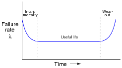
While the “Useful life” and “Wear-out” phases of the system life-cycle are easy to understand, the initial “Infant mortality” phase is not so intuitive. Explain what factors might lead to premature component failure during this initial phase of a system’s lifespan.
Reveal answerGross manufacturing defects, incorrect installation, and design flaws, to name a few.
Follow-up question: is it important to know which phase of the life-cycle a system is in before you begin to troubleshoot a problem in it? Explain your answer.
Notes:The follow-up question is especially important to discuss with your students. Knowing what portion of the life-cycle a system is in can make a huge difference in your troubleshooting effectiveness. Ask your students why this is. If possible, enlighten the discussion with examples from your own professional experience.
-
Question 6
For the following electronic components, determine whether they are more likely to fail open or fail shorted (this includes partial, or high-resistance, shorts):
- Resistors:
- Capacitors:
- Inductors:
- Switches:
- Transformers:
- Diodes:
- Bipolar transistors:
- Field-effect transistors:
- Crystals:
I encourage you to research information on these devices’ failure modes, as well as glean from your own experiences building and troubleshooting electronic circuits.
Reveal answerRemember that each of these answers merely represents the most likely of the two failure modes, either open or shorted, and that probabilities may shift with operating conditions (i.e. switches may be more prone to failing shorted due to welded contacts if they are routinely abused with excessive current upon closure).
- Resistors: open
- Capacitors: shorted
- Inductors: open or short equally probable
- Switches: open
- Transformers: open or short equally probable
- Diodes: shorted
- Bipolar transistors: shorted
- Field-effect transistors: shorted
- Crystals: open
Notes:Emphasize to your students how a good understanding of common failure modes is important to efficient troubleshooting technique. Knowing which way a particular component is more likely to fail under normal operating conditions enables the troubleshooter to make better judgments when assessing the most probable cause of a system failure.
Of course, proper troubleshooting technique should always reveal the source of trouble, whether or not the troubleshooter has any experience with the failure modes of particular devices. However, possessing a detailed knowledge of failure probabilities allows one to check the most likely sources of trouble first, which generally leads to faster repairs.
A division of the United States Department of Defense (DoD) as the Reliability Analysis Center, or RAC, publishes detailed analyses of failure modes for a wide variety of components, electronic as well as non-electronic. They may be contacted at 201 Mill Street, Rome, New York, 13440-6916. Data for this question was gleaned from the RAC’s 1997 publication, Failure Mode / Mechanism Distributions (FMD-97).
-
Question 7
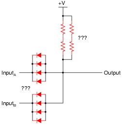
The Orbiting Astronomical Observatory was a NASA project during the late 1960’s and 1970’s to place precision observational instruments in earth orbit for scientific purposes. Satellites designed for this program had to have “hardened” circuitry to withstand the radiation, extreme temperatures, and other harsh conditions of space.
An example of some of this “fail-safe” circuitry is shown here: a passive, quad-redundant, two-input AND gate:

First, draw a schematic for a non-redundant, passive AND gate. Which components shown in the above schematic are “redundant,” and which are essential?
Then, explain why the circuit is referred to as quad-redundant. How many individual component failures, minimum, must occur before the gate’s functionality is compromised? Prove your answer through an analysis of the circuit’s operation.
Reveal answerThis is the schematic for a non-redundant, passive AND gate:

Follow-up question: why do you suppose transistors were eliminated from this gate circuit’s design?
Challenge question: note that there are series-parallel clusters of four diodes in the quad-redundant gate circuit, where there only needs to be one for minimum functionality. Note also that the four resistors are all in parallel, not in a series-parallel arrangement. Why is this? Why not cluster all four diodes in parallel instead of series-parallel? Why not cluster the four resistors in series-parallel, instead of simple parallel?
Notes:It is worth discussing with your students how a passive gate such as this functions at all. Ask your students whether this gate requires the input signals to be current-sourcing or current-sinking, and whether or not the passive nature of the circuit constitutes a problem interfacing it with other logic circuits.
The challenge question is a very good one to discuss in class with all your students. The answer to why the diodes are in a series-parallel arrangement should be fairly easy to understand. Why the resistors can be simply paralleled is a bit more complex to answer. The key to understanding both these design features lies in the typical failure modes of each component type.
-
Question 8
One use for “rectifying” diodes is to parallel multiple power supplies for extra reliability in powering a critical system:
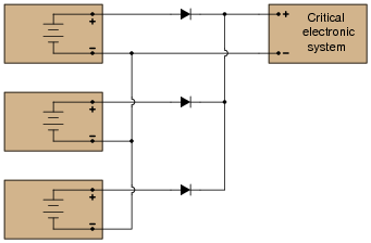
However, as an experienced electronics technician, you should know that diodes are not immune to failure. Modify this schematic diagram to include three extra (redundant) diodes that will allow normal operation if any one of the three original diodes were to fail, assuming the most common failure mode of rectifier-type diodes.
Reveal answerThe best way to wire pairs of rectifying diodes together for redundancy is in series:
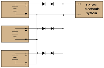
Notes:While this may seem like “overkill,” to use redundant diodes on redundant power supplies, it is a design feature that does not cost very much. Given the measurable improvement in reliability with minimal increase in cost, this design feature is not unreasonable.
-
Question 9
The Orbiting Astronomical Observatory was a NASA project during the late 1960’s and 1970’s to place precision observational instruments in earth orbit for scientific purposes. Satellites designed for this program had to have “hardened” circuitry to withstand the radiation, extreme temperatures, and other harsh conditions of space.
An example of some of this “fail-safe” circuitry is shown here: a quad-redundant inverter (NOT) gate:
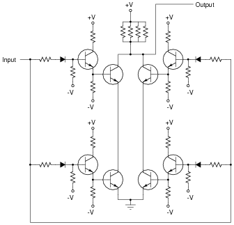
Explain why the circuit is referred to as quad-redundant. How many individual component failures, minimum, must occur before the gate’s functionality is compromised? Prove your answer through an analysis of the circuit’s operation.
Reveal answerIf you analyze this circuit carefully, you will find that it may actually fail with just two component faults, if they are the right type of fault, in the right locations!
Notes:This circuit is a good one to discuss with your students in class. Ask them to explain its basic operation: if all components are functioning properly, what happens when it receives a “high” input, versus a “low” input? Do the input signals need to be current-sourcing or current-sinking? What about the output of this circuit: does it source or sink current?