Facebook
 Google
 GitHub
 Linkedin
Digital Circuits
Time-Delay Electromechanical Relays
19 questions By Tony R. Kuphaldt
-
Question 1 of 19
What does the normal status of an electrical switch refer to? Specifically, what is the difference between a normally-open switch and a normally-closed switch?
Reveal answerThe “normal” status of a switch refers to the open or closed status of the contacts when there is no actuating force applied to the switch.
Notes:An important qualification for an electrical switch to be either “normally-open” or “normally-closed” is that it have a spring to return it to its “normal” state in the absence of an actuating force. Latching switches such as most toggle switches really cannot be defined in terms of “normally-” anything. Discuss this with your students, possibly showing them some examples of momentary contact switches that are either N.O. or N.C.
-
Question 2 of 19
A special class of electromechanical relays called time-delay relays provide delayed action, either upon power-up or power-down, and are commonly denoted in ladder logic diagrams by “TD” or “TR” designations near the coil symbols and arrows on the contact symbols. Here is an example of a time-delay relay contact used in a motor control circuit:

In this circuit, the motor delays start-up until three seconds after the switch is thrown to the “Run” position, but will stop immediately when the switch is returned to the “Stop” position. The relay contact is referred to as normally-open, timed-closed, or NOTC. It is alternatively referred to as a normally-open, on-delay contact.
Explain how the arrow symbol indicates the nature of this contact’s delay, that delay occurs during closure but not during opening.
Reveal answerNote that the “Arrow” is pointing in the up direction, toward the direction of contact closure.
Notes:The arrow symbol is not difficult to figure out, but it is essential to know when working with time-delay relay circuits. Ask your students to describe their understanding of the arrow symbol as they answer this question.
-
Question 3 of 19
Match the following time-delay relay contact type symbols and labels:

- Normally-open, timed-closed
- Normally-open, timed-open
- Normally-closed, timed-closed
- Normally-closed, timed-open
Reveal answer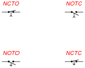
Follow-up question: how do you make sense of the arrow in each contact symbol, with regard to whether the contact is timed-open or timed-closed?
Notes:Ask your students to present their personal explanations of how to make sense of the arrow directions, in relation to whether the relay is “timed-open” or “timed-closed.” The correlation is really not that complex, but it is a good thing to clearly elaborate on it for the benefit of the whole class. You may want to re-phrase the question like this: “Does the arrow represent the direction of timed motion or the direction of instantaneous motion?”