Facebook
 Google
 GitHub
 Linkedin
Digital Circuits
Timer Circuits
18 questions By Tony R. Kuphaldt
-
Question 4 of 18
The type “555” integrated circuit is a highly versatile timer, used in a wide variety of electronic circuits for time-delay and oscillator functions. The heart of the 555 timer is a pair of comparators and an S-R latch:

The various inputs and outputs of this circuit are labeled in the above schematic as they often appear in datasheets (“Thresh” for threshold, “Ctrl” or “Cont” for control, etc.).
To use the 555 timer as an astable multivibrator, simply connect it to a capacitor, a pair of resistors, and a DC power source as such:

If were were to measure the voltage waveforms at test points A and B with a dual-trace oscilloscope, we would see the following:
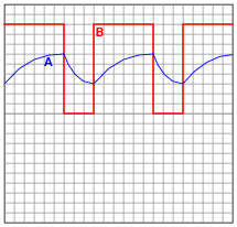
Explain what is happening in this astable circuit when the output is “high,” and also when it is “low.”
Reveal answerWhen the output is high, the capacitor is charging through the two resistors, its voltage increasing. When the output is low, the capacitor is discharging through one resistor, current sinking through the 555’s “Disch” terminal.
Follow-up question: algebraically manipulate the equation for this astable circuit’s operating frequency, so as to solve for R2.
f = 1 (ln2)(R1 + 2R2)CChallenge question: explain why the duty cycle of this circuit’s output is always greater than 50%.
Notes:This popular configuration of the 555 integrated circuit is well worth spending time analyzing and discussing with your students.
-
Question 5 of 18
This astable 555 circuit has a potentiometer allowing for variable duty cycle:

With the diode in place, the output waveform’s duty cycle may be adjusted to less than 50% if desired. Explain why the diode is necessary for that capability. Also, identify which way the potentiometer wiper must be moved to decrease the duty cycle.
Reveal answerThe diode allows part of the potentiometer’s resistance to be bypassed during the capacitor’s charging cycle, allowing (potentially) less resistance in the charging circuit than in the discharging circuit.
To decrease the duty cycle, move the wiper up (toward the fixed resistor, away from the capacitor).
Challenge question: write an equation solving for the average current drawn by the 555 timer circuit as it charges and discharges the capacitor while generating a 50% duty cycle pulse. Assume that no current is drawn from the power supply by the circuit while the capacitor is discharging, and use this approximation of the capacitor “Ohm’s Law” equation for figuring average current through the charge cycle:
i = C dv dtTrue “Ohm′s Law” for a capacitor Iavg = C ∆V ∆tCapacitive Öhm′s Law” solving for average current Notes:This question really probes students’ conceptual understanding of the 555 timer, used as an astable multivibrator (oscillator). If some students just can’t seem to grasp the function of the diode, illuminate their understanding by having them trace the charging and discharging current paths. Once they understand which way current goes in both cycles of the timer, they should be able to recognize what the diode does and why it is necessary.
-
Question 6 of 18
A popular use of the 555 timer is as a monostable multivibrator. In this mode, the 555 will output a pulse of fixed length when commanded by an input pulse:
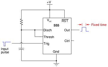
How low does the triggering voltage have to go in order to initiate the output pulse? Also, write an equation specifying the width of this pulse, in seconds, given values of R and C. Hint: the magnitude of the supply voltage is irrelevant, so long as it does not vary during the capacitor’s charging cycle. Show your work in obtaining the equation, based on equations of RC time constants. Don’t just copy the equation from a book or datasheet!
Reveal answerThe triggering pulse must dip below 1/3 of the supply voltage in order to initiate the timing sequence.
tpulse = 1.1RC Notes:Have your students show you how they mathematically derived their answer based on their knowledge of how capacitors charge and discharge. Many textbooks and datasheets provide this same equation, but it is important for students to be able to derive it themselves from what they already know of capacitors and RC time constants. Why is this important? Because in ten years they won’t remember this specialized equation, but they will probably still remember the general time constant equation from all the time they spent learning it in their basic DC electricity courses (and applying it on the job). My motto is, “never remember what you can figure out.”
Related Tools:
- Step-up, Step-down, and Isolation Transformers
- Design Project: Simple Component Curve-Tracer Circuit