Facebook
 Google
 GitHub
 Linkedin
Discrete Semiconductor Devices and Circuits
Design Project: Simple Component Curve-Tracer Circuit
-
Question 1
What do each of the oscilloscope axes represent, in real-life terms (variables and units) when used in conjunction with this curve tracer circuit?
Reveal answerHorizontal axis: voltage applied across terminals of device under test (1 volt displayed = 1 volt).
Vertical axis: current through device under test (1 volt displayed = 1 mA)
Notes:The resistor’s specified value of 1 kΩ should make perfect sense when students see the voltage:current ratio for the vertical axis!
-
Question 2
What mode does the oscilloscope have to be set in, in order to use with this curve tracer circuit?
Reveal answerThe oscilloscope needs to be set in the “X-Y” mode.
Notes:It is important for students to realize that the oscilloscope will not produce the desired display if configured for the normal “time-domain” display. For the circuit to be able to work, the curve tracer must provide the horizontal sweep, hence the dual inputs to the oscilloscope.
-
Question 3
If quantitative accuracy is desired from this curve tracing circuit, the shunt resistor should be precisely 1 kΩ in size. Explain how a precise shunt resistance may be built without the use of precision components (i.e. a special 1 kΩ precision resistor).
Reveal answerHint: there’s a saying in the electronics world that goes something like this: “Don’t make it precise, make it adjustable!”
Notes:Though it may have been a while since you last discussed how to achieve precise (adjustable!) values of resistance from non-precision resistors, students should at least remember the general concept if not the exact implementation.
-
Question 4
When testing this circuit for the first time, the student connects a 1 kΩ resistor to the two test leads and gets this result from the oscilloscope display:
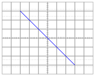
The student was actually expecting something that looked like this:
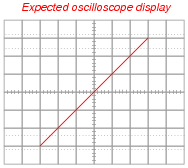
Upon inspection, nothing appears to be wrong with the wiring of the curve tracer circuit. Explain what the problem is so the student is able to achieve the expected results.
Reveal answerOne of the oscilloscope’s two input channels must be inverted for the curve tracer to work as expected. Most oscilloscopes come equipped with an “invert” control on the second input channel that is used for this purpose.
Follow-up question: is the curve tracer circuit configured for an AC test or a DC test, based on the appearance of the oscilloscope trace?
Notes:This circuit provides an excellent opportunity for students to discuss and review the common grounds of oscilloscope inputs, and why one of the oscilloscope’s inputs must be wired “backward” in order to yield the expected trace from lower-left to upper-right.
-
Question 5
Explain why the wave-shape of the excitation voltage is irrelevant to the operation of this curve tracing circuit. The transformer happens to output the same sine wave shape exhibited by the AC line power, but the circuit would work equally wall with a triangle wave, sawtooth wave, or badly distorted sine wave.
Reveal answerAll that is needed is some sort of wave-shape that sweeps the oscilloscope beam to and fro. Since the relationship between vertical displacement and horizontal displacement on the oscilloscope’s trace is purely a function of the test component’s characteristic curve, we really don’t care what form of AC voltage excites it.
Notes:Dedicated curve tracer circuits typically use a sawtooth waveform (much like the waveform used to sweep an oscilloscope beam horizontally in the normal “time-domain” mode), so that the brightness of the trace is relatively even throughout. This is why a square-wave excitation would not work well: most of the trace would be extremely dim and hard to see, with the endpoints of the curve being the only bright spots!sawtotj