Facebook
 Google
 GitHub
 Linkedin
Digital Circuits
TTL Logic Gates
25 questions By Tony R. Kuphaldt
-
Question 16 of 25
Explain why it is generally a very bad design practice to connect the outputs of different logic gates together, like this:

However, there are certain specific circumstances in which “paralleling” gate outputs is acceptable. For instance, it is okay to parallel two or more inverters, like this:

No damage will be done if open-collector gate outputs are paralleled, either (although the resulting logic function may be strange):

And finally, gates that have tri-state outputs may also have their outputs paralleled if certain precautions are taken:

What, specifically, causes gates to be damaged by “paralleling” their outputs? Generally speaking, what principle must be followed in order to “parallel” logic gate outputs without risk of damage? Explain how each of the three acceptable “paralleled” scenarios shown here meet this criterion.
Suggestion: the issue of multiple gates having to output logic voltage signals onto common conductors (“busses”) is called bus contention. Try looking for this term in your research to see what useful information you find on paralleled gates!
Reveal answerLogic gates will be damaged if one tries to sink the output current sourced by another.
Notes:The given answer cuts to the heart of the matter, but I want students to elaborate on the details. Specifically, why each of the three acceptable paralleled circuits avoids risk of damage. Make sure you spend adequate time discussing “tri-state” outputs as well. Ask your students to explain what the three output states of a “tri-state” gate are.
-
Question 17 of 25
An important parameter of logic gate circuitry is noise margin. What exactly is “noise margin,” and how is it defined for logic gates?
Specifically, how much noise margin do digital circuits exclusively composed of TTL gates have?
Note: you will need to consult TTL gate datasheets to answer this question properly.
Reveal answerNoise margin is the difference between the acceptable voltage limits for corresponding input and output logic states.
Notes:This question, to be answered properly, involves more than just a definition of “noise margin.” Students must first discover that there is a difference between voltage compliance levels for gate inputs versus outputs, then recognize that the difference constitutes a “margin” that imposed AC voltage (“noise”) must not exceed. They must then present their answer in terms of manufacturer specifications, obtained in datasheets. In summary, there is a lot of research that must occur to answer this question, but the results will be worth it!
-
Question 18 of 25
Predict how the operation of this logic gate circuit will be affected as a result of the following faults. Consider each fault independently (i.e. one at a time, no multiple faults):
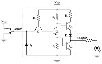
- Diode D1 fails open:
- Diode D1 fails shorted:
- Diode D2 fails open:
- Resistor R1 fails open:
- Resistor R2 fails open:
- Resistor R4 fails open:
For each of these conditions, explain why the resulting effects will occur.
Reveal answer- Diode D1 fails open: No effect.
- Diode D1 fails shorted: Output always in high state, possible damage to circuit when input switch is in high state.
- Diode D2 fails open: Gate can sink current in low output state, but cannot source current in high output state.
- Resistor R1 fails open: Output always in high state.
- Resistor R2 fails open: Gate can sink some current in low output state, but cannot source current in high output state. Gate may have trouble attaining a solid “low” output state as well.
- Resistor R4 fails open: Limited ability to source current in high output state.
Notes:The purpose of this question is to approach the domain of circuit troubleshooting from a perspective of knowing what the fault is, rather than only knowing what the symptoms are. Although this is not necessarily a realistic perspective, it helps students build the foundational knowledge necessary to diagnose a faulted circuit from empirical data. Questions such as this should be followed (eventually) by other questions asking students to identify likely faults based on measurements.