Facebook
 Google
 GitHub
 Linkedin
Digital Circuits
TTL Logic Gates
25 questions By Tony R. Kuphaldt
-
Question 19 of 25
Predict how the operation of this logic gate circuit will be affected as a result of the following faults. Consider each fault independently (i.e. one at a time, no multiple faults):
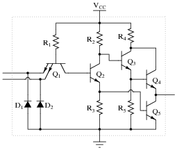
- Diode D1 fails open:
- Diode D1 fails shorted:
- Diode D2 fails open:
- Resistor R1 fails open:
- Resistor R2 fails open:
- Transistor Q2 emitter terminal fails open:
- Transistor Q3 emitter terminal fails open:
For each of these conditions, explain why the resulting effects will occur.
Reveal answer- Diode D1 fails open: No effect.
- Diode D1 fails shorted: Output always in high state, possible damage to circuit when input switch is in high state.
- Diode D2 fails open: No effect.
- Resistor R1 fails open: Output always in high state.
- Resistor R2 fails open: Gate can sink some current in low output state, but cannot source current in high output state. Gate may have trouble attaining a solid “low” output state as well.
- Transistor Q2 emitter terminal fails open: Output always in high state.
- Transistor Q3 emitter terminal fails open: Gate can sink current in low output state, but cannot source current in high output state.
Notes:The purpose of this question is to approach the domain of circuit troubleshooting from a perspective of knowing what the fault is, rather than only knowing what the symptoms are. Although this is not necessarily a realistic perspective, it helps students build the foundational knowledge necessary to diagnose a faulted circuit from empirical data. Questions such as this should be followed (eventually) by other questions asking students to identify likely faults based on measurements.
-
Question 20 of 25
In TTL circuitry, one side of the DC power supply is usually labeled as “VCC”, while the other side is labeled as “VEE”. Why is this? What do the subscripts “CC” and “EE” represent?
Reveal answerVCC = Power supplied to collector side of bipolar transistors.
VEE = Power supplied to emitter side of bipolar transistors.
Follow-up question: Since TTL circuits use NPN transistors exclusively, what polarities must each of these labels represent?
Notes:This question is a good review of bipolar junction transistor theory.
-
Question 21 of 25
True story: once upon a time, there was a machine shop containing a number of computer-controlled machine tools (lathes, mills, grinders, etc.), where one of the machines proved to be very “finicky” when starting. Sometimes, it would function properly when you pushed the “Start” button, and other times it refused to work at all. The problem was so bad, it got to the point where the machinists responsible for operating this tool became almost superstitious about it, performing a ritual dance before pressing the “Start” button, whimsically hoping to improve their luck.
An electrician was called to service this machine, but he could find nothing wrong with the electrical power circuitry. All of the high-voltage equipment (transformers, relays, motors, motor control circuits, etc.) seemed to be in good working order. The problem, whatever it was, resided within the machine’s electronic control computer. The computer was not sending the “start” signal to the motor control circuits when the “Start” button was pushed.
An electronics technician was called to troubleshoot the computer, and he was able to fix it in a matter of minutes. The problem, he said, was the computer’s DC power supply: the voltage regulator was out of adjustment. With just a twist of a potentiometer, the technician was able to “trim” the regulated voltage to 5.00 volts, right where it should be for TTL circuitry.
The power supply voltage was not very far from 5.00 volts before the technician adjusted it. How far is the supply voltage allowed to deviate for TTL logic circuits, and still have guaranteed proper operation? Consult one or more IC datasheets for legacy TTL logic circuits (not the newer high-speed CMOS 54HCxx and 74HCxx chips) to obtain your answer.
Reveal answerI’ll let you do your own research on this question. DO NOT obtain your answer from a textbook, but consult a manufacturer’s datasheet instead!
Notes:This true story was told to me by one of my former students, who had some previous experience with electronics maintenance prior to enrolling in my class. The moral of this story, of course, is the sensitivity of TTL logic circuits to power supply voltage variations. This will (and should!) surprise many of your students, who are probably used to seeing the rather wide voltage limits of opamps and other analog circuitry.