Facebook
 Google
 GitHub
 Linkedin
Digital Circuits
TTL Logic Gates
25 questions By Tony R. Kuphaldt
-
Question 10 of 25
A student builds the following digital circuit on a solderless breadboard (a “proto-board”):
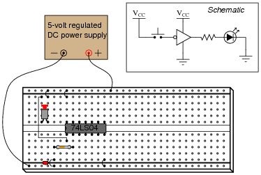
The DIP circuit is a TTL hex inverter (it contains six “inverter” or “NOT” logic gates), but only one of these gates is being used in this circuit. The student’s intent was to build a logic circuit that energized the LED when the pushbutton switch was unactuated, and de-energized the LED when the switch was pressed: so that the LED indicated the reverse state of the switch itself. However, in reality the LED fails to energize no matter what state the switch is in.
First question: how would you use a multimeter as a logic probe to check the logic states of points in this circuit, in order to troubleshoot it?
Second question: suppose you checked the logic states of pin #1 on the IC, for both states of the switch (pressed and unpressed), and found that pin #1 was always “high”. How does this measurement indicate the student’s design flaw in this circuit? How would you recommend this design flaw be corrected?
Reveal answerTo use a multimeter as a logic probe, connect the common (black) test lead to the power supply ground, set the meter to measure DC voltage (a 0-5 volt scale would be perfect in this application), and then use the other test lead (red) to probe the various points of the circuit.
The problem with this student’s circuit is the input switch: it does not provide a solid “low” state when open. Rather, the inverter’s input is left “floating” when the switch is unactuated. There is more than one way to fix this design flaw, but I’ll leave the details up to you!
Notes:Discuss the problem of “floating” or “high-Z” states with your students. It is always a good idea to eliminate ambiguous logic states such as this in the circuits you build.
-
Question 11 of 25
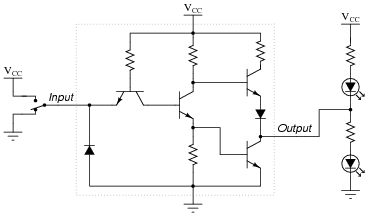
Draw the paths of all currents in this circuit with the input in a “low” state:
Now, draw the paths of all currents in this circuit with the input in a “high” state:
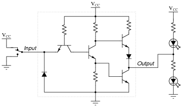
Where is the power supplied for each LED? What relationship is there between the load current (LED) and the gate input current (through the SPDT switch)?
Also, explain how you would calculate the values for appropriate LED current-limiting resistors in this circuit.
Reveal answer

In each scenario, the LED’s power is supplied by VCC and ground: the DC power source. Note that the input switch merely “tells” the output what to do rather than handle actual load current, just like the inputs of an operational amplifier or comparator.
Notes:The utility of conventional flow notation (as opposed to electron flow) becomes especially apparent in this answer, as the upper circuit is the one sourcing current and the lower circuit is the one sinking current.
As with operational amplifiers, I find it necessary to point out to some students that the inputs of a logic gate circuit do not sink or source load current. This fact underscores the need to supply DC power to the logic gate for proper operation.
-
Question 12 of 25
The digital circuit shown here is a unanimous-yea vote detector. Votes are cast by eight different voters by the setting of switches in either the closed (yea) or open (nay) positions. According to the logic function provided by the TTL gates, the LED will energize if and only if all switches are closed:

As is common in digital circuit schematics, the power supply (VCC) is omitted for the sake of simplicity. This is analogous to the omission of power supply connections in many operational amplifier circuit schematics.
If we were to draw a truth table for this circuit, how large (number of rows and columns) would the table have to be?
Suppose we wished to modify this circuit, such that an electromechanical bell would ring whenever a unanimous-yea vote was cast, rather than merely lighting a small LED. The bell we have in mind to use is rather large, its solenoid coil drawing 3 amps of current at a voltage of 12 volts DC: well beyond the final gate’s ability to source. How could we modify this circuit so that the final gate is able to energize this bell instead of just an LED?
Reveal answer
Follow-up question: explain why pullup resistors are not required in this circuit.
Challenge question: sometimes engineers and technicians alike overlook the most elegant (beautifully simple) solutions in their quest to solve a problem. The solution shown here, while practical, solves the problem by adding components to the circuit. Can you think of a way we might build a unanimous-yea vote detector using fewer components than the original LED circuit?
Notes:Ask your students why we might want to use a Darlington pair instead of a single transistor for the final output “driver” circuit. Also, ask them why we need to have a resistor connected between the gate output and the transistor base. Why not just directly connect the gate’s output to the base of the transistor?
You might want to challenge your students with this question: “Suppose the person who built this circuit used open-collector gates throughout. As a whole, it would not function, neither for lighting the LED nor for ringing the bell. However, only one of the gates would need to have the standard `totem-pole’ output in order for the circuit to function properly. Which gate is it?”