Facebook
 Google
 GitHub
 Linkedin
Digital Circuits
TTL Logic Gates
25 questions By Tony R. Kuphaldt
-
Question 22 of 25
In this circuit, an AND gate is used to give a toggle switch control over the blinking of an LED:
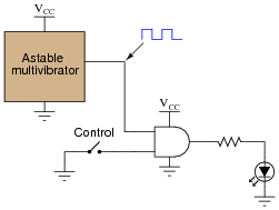
The “astable multivibrator” is nothing more than an oscillator that produces a square-wave signal at a low frequency, at standard TTL voltage levels (0 and 5 volts).
Plot the output waveform for the gate (i.e. the voltage signal to the LED), given the following input conditions:
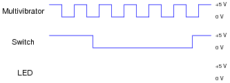
Hint: it helps in your analysis of digital waveforms if you first write a truth table for the gate under consideration, for your reference.
Reveal answer
Notes:Many students find the waveform analysis of digital circuits intimidating at first, until they understand that it is nothing more than a graphical representation of “0” and “1” logic states over time. Ask your students to share their “tips” on how to relate waveforms to truth tables, and in particular how they answered this particular question.
Just for fun, you might want to ask your students to identify where in time the toggle switch is open, and where it is closed. Some students may answer backwards to this question, if they haven’t carefully considered how the toggle switch is connected in this circuit!
-
Question 23 of 25
What does it mean if you see a logic gate symbol in a schematic diagram with a strange-looking “S” figure drawn inside of it?

Reveal answerThe “S” figure, which resembles a magnetic B-H hysteresis curve, marks this gate as a Schmitt trigger. I’ll let you do the research to determine what this means in regard to gate function.
Notes:Schmitt trigger gates are indispensable for certain logic circuit applications. It is important that students recognize their function and utility.
Incidentally, this question provides a good opportunity to review magnetic hysteresis curves, since it’s probably been awhile since students last studied electromagnetism theory!
-
Question 24 of 25
For a true TTL gate (not high-speed CMOS), what is the default logic state of an input line that is left floating (neither connected to VCC nor Ground)? Explain why this is.
Reveal answerFloating TTL inputs generally assume a “high” state due to the steering diode/resistor network on the input stage of each gate circuit.
Notes:The given answer does not provide enough detail to explain why TTL inputs tend to float high, so I recommend you display an internal TTL gate schematic for your students to analyze and comment on in class.