Facebook
 Google
 GitHub
 Linkedin
555 Lab - Schmitt Trigger
Project Overview
In this project, you will build a Schmitt trigger using a 555 timer integrated circuit (IC). A Schmitt trigger is a special analog comparator with hysteresis. This means that it has different switching threshold voltages depending upon whether the input is changing from low to high or high to low, as illustrated in Figure 1.
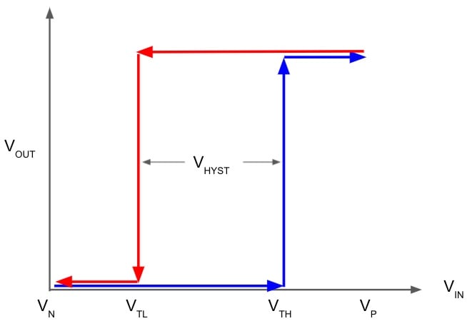
Figure 1. Input-output voltage relationship for a Schmitt trigger.
The Schmitt trigger uses positive feedback to generate this nonlinear response. The input voltage for the low-to-high transition is called the high threshold voltage (VTH). The high-to-low transition input voltage is called the low threshold voltage (VTL).
The schematic symbol for an inverting Schmitt trigger, shown in Figure 2, is an inverter symbol with a hysteresis curve in the middle.
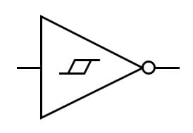
Figure 2. The schematic symbol for a Schmitt trigger.
The 555 timer is probably one of the more versatile “black box” chips. In this project, we will use the 555 timer's 3-resistor voltage divider, two comparators, and a built-in set-reset flip-flop to form a Schmitt trigger. It is also easy to build a Schmitt trigger using an operational amplifier with positive feedback.
Parts and Material
- One 9 V battery
- Battery clip
- Mini hook clips
- One linear potentiometer, 10 kΩ, 15-Turn
- One 555 timer IC
- One red light-emitting diode (LED)
- One green LED
- Two 1 kΩ resistors
- One DVM (digital voltmeter) or VOM (Volt Ohm Meter)
Learning Objectives
- Learn how a Schmitt trigger works
- How to use the 555 timer as a Schmitt trigger
Instructions
First, let's build the circuit demonstrated in the schematic diagram of Figure 3.
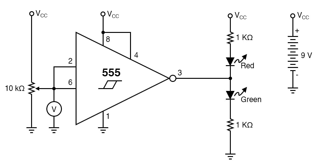
Figure 3. Schmitt trigger circuit with potentiometer input and LED output indicators.
In this image, the 555 timer is represented by a modified Schmitt trigger with a few extra pins to help the circuit make sense. The input of the Schmitt trigger is connected to the potentiometer, which will be used to vary the input. When the output is high, it will turn on the green LED. When the output is low, it will turn on the red LED.
Step 1: Build the circuit illustrated by the schematic diagram of Figure 4 and the breadboard implementation of Figure 5.
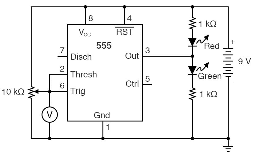
Figure 4. Schematic diagram of the Schmitt trigger circuit built using a 555 timer.
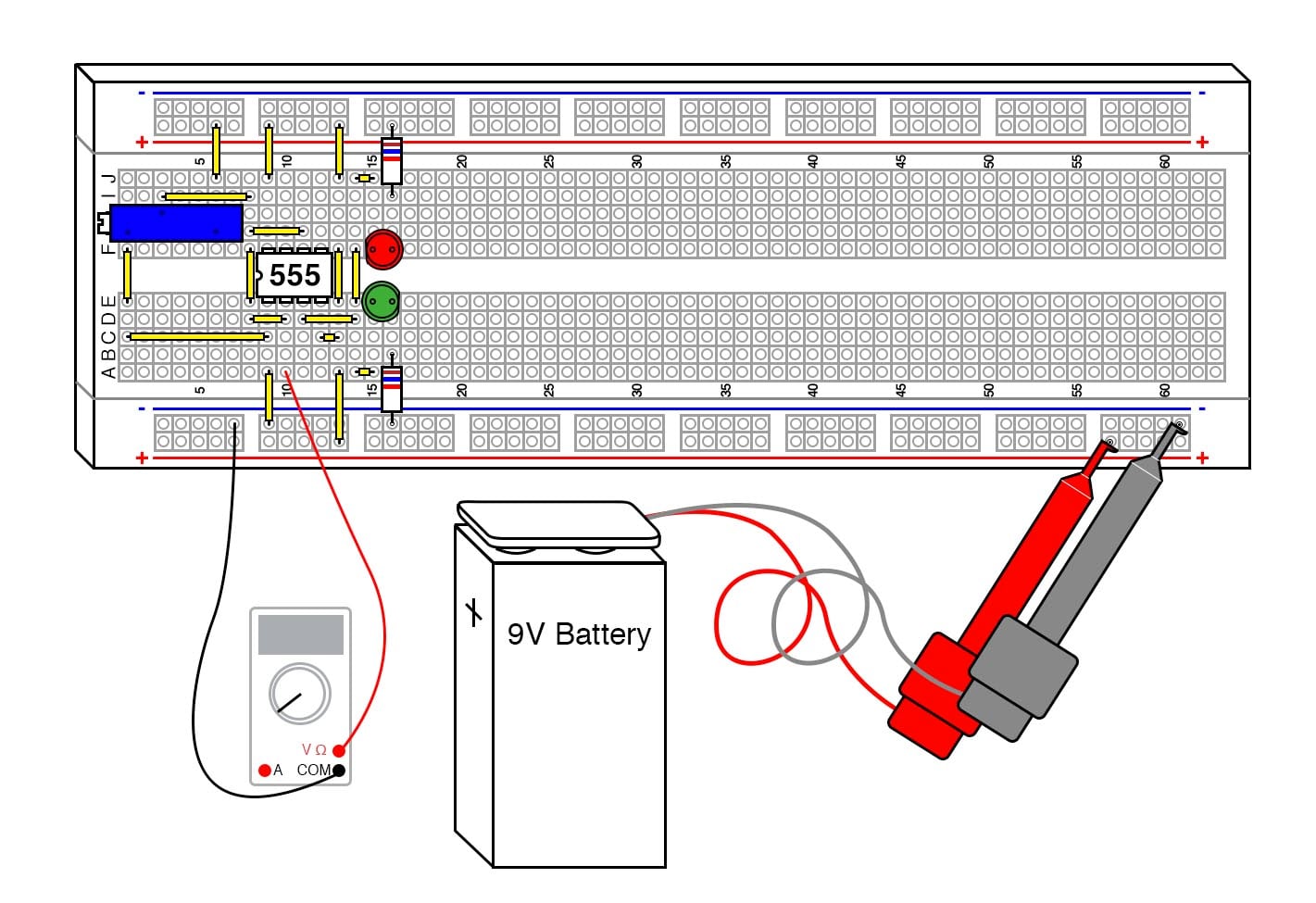
Figure 5. Breadboard implementation of the Schmitt trigger circuit with LED output indicators.
It’s interesting to note that this configuration of a Schmitt trigger isn’t even close to the operational amplifier (op amp) configuration shown elsewhere, but the end result is identical.
Step 2: Adjust the potentiometer until the lights flip states, then measure the potentiometer output voltage. Compare this voltage to the power supply voltage.
Step 3: Adjust the potentiometer in the other direction until the LED’s flip states again, and again measure the voltage. How close to the 1/3 and 2/3 marks did you get?
Step 4: Try substituting the 9 V battery with a 6 V battery or two 6 V batteries, and see how close the thresholds are to the 1/3 and 2/3 marks.
Theory of Operation
Figure 6 provides a functional circuit schematic of the inner workings of the 555 timer IC, which will help to understand how our 555 Schmitt trigger is operating.
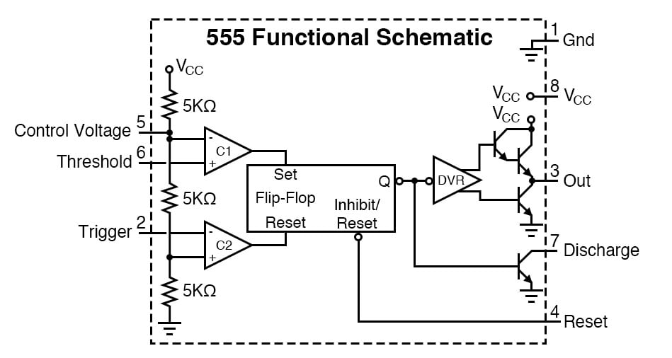
Figure 6. A functional circuit schematic of the 555 timer IC.
The defining characteristic of any Schmitt Trigger is its hysteresis. In this case, it is 1/3 and 2/3 of the power supply voltage, defined by the built-in resistor voltage divider on the 555 IC. The built-in comparators, C1 and C2, compare the input voltage to the references provided by the voltage divider. The outputs of C1 and C2 drive the set and reset inputs of the built-in flip-flop, respectively. The output of the flip-flop drives the output driver, another nice feature of the 555.
The 555 can drive up to 200 mA to either side of the power supply rail (VCC or GND). The output driver creates a very low conduction path to either side of the power supply connections.
The circuit "shorts” each side of the LED circuit, leaving the other side to light up. The 5 kΩ resistors are not very accurate. However, it is interesting to note that IC fabrication doesn’t generally allow precision resistors, but the resistors compared to each other are extremely close in value, which is critical to the circuit’s operation. Thus, the ratio is quite accurate even if the values are not precisely 5 kΩ.
Schmitt triggers are a fundamental circuit with several uses. In signal processing, they can pull and extract digital data from some extremely noisy environments. The hysteresis reduces the amount of noise that is passed to the output. Other important uses will be shown in the following projects, such as an extremely simple RC oscillator.
Related Content
Learn more about the fundamentals behind this project in the resources below.
Textbook:
Calculator:
Industry Article:
Worksheets: