Facebook
 Google
 GitHub
 Linkedin
555 Lab - Oscillator With Hysteresis
Project Overview
This project introduces the design of one of the most basic RC oscillators, an astable multivibrator, which is simple and predictable. As illustrated in Figure 1, the circuit uses a 555 timer as its central component and includes red and green light-emitting diodes (LEDs) for output indicators.
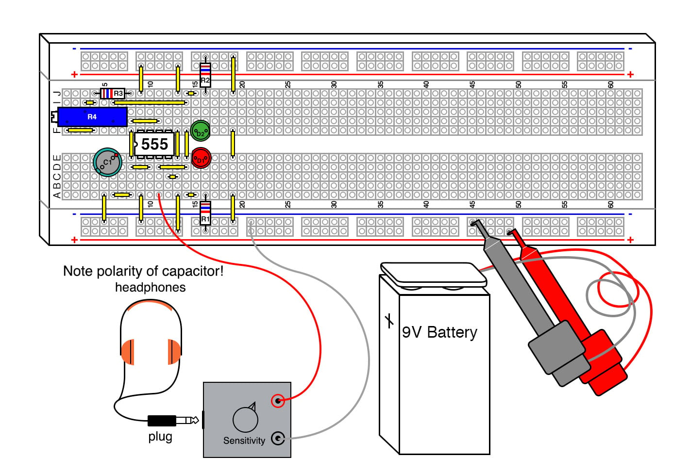
Figure 1. Breadboard implementation of the 555 timer oscillator with hysteresis.
A potentiometer allows easy frequency adjustment of the oscillator. The sensitivity detector with headphones is optional.
Any inverting Schmitt trigger will work in this design, although the frequency will shift somewhat depending on the hysteresis of the gate.
Parts and Materials
- One 9 V battery
- Battery clip
- Mini-hook clips, soldered to the battery clip
- U1 - 555 timer IC
- D1 - red light-emitting diode
- D2 - green light-emitting diode
- R1, R2 - 1 kΩ 1/4 W resistors
- R3 - 10 Ω 1/4 W resistor
- R4 - 10 kΩ, 15-turn potentiometer
- C1 - 1 µF capacitor
- C1 - 100 µF capacitor
Learning Objectives
- How to use a Schmitt trigger for a simple RC oscillator
- Learn a practical application for an RC time constant
- Learn one of several 555 timer astable multivibrator configurations
Instructions
Step 1: Build the circuit illustrated in the circuit schematic of Figure 2 and illustrated in the breadboard implementation of Figure 1 above.
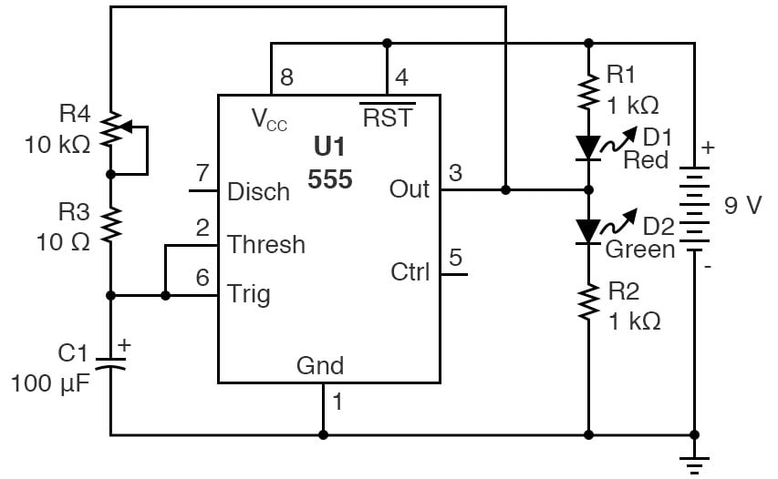
Figure 2. Schematic diagram of the 555 timer oscillator with hysteresis.
Figure 3 is an alternative schematic diagram with the 555 timers represented as a modified Schmitt trigger with extra pins required by the 555 timer to implement the Schmitt trigger function.
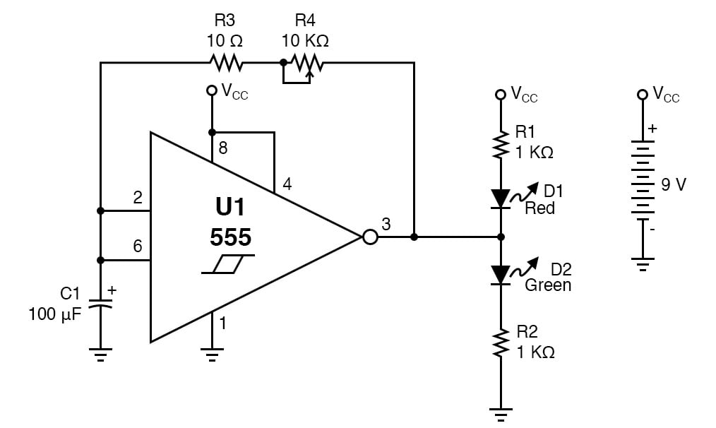
Figure 3. Schematic diagram of the 555 timer oscillator with hysteresis using a Schmitt trigger representation.
Step 2: This circuit has a lower-end frequency of 0.7 Hz, which means each LED will alternate and be lit for just under a second. Begin with the potentiometer turned to its highest resistance value. The 555 does not go rail to rail (it doesn’t quite reach the upper supply voltage) because of its output Darlington transistors, and this causes the oscillator square wave to be not quite symmetrical. Can you see this by looking at the LEDs?
The higher the power supply voltage, the less pronounced this asymmetry is, while it gets worse with lower power supply voltages. If the output were true rail to rail, it would be a 50% square wave, which can be attained if one uses the complementary metal-oxide semiconductor (CMOS) version of the 555, such as the TLC555.
Step 3: As you turn the potentiometer counterclockwise, the frequency will increase, going well into the high-end audio range. As this frequency gets too high, the LEDs will flash too quickly to observe the changes in frequency. You can verify this with an oscilloscope, an audio detector, or a piezoelectric speaker. If you monitor the frequency with the audio detector or speaker, as you continue to turn the potentiometer, the pitch of the sound will rise.
Step 4: You can increase the frequency 100 times by replacing the 100 µF capacitor with the 1 µF capacitor, which will also raise the maximum frequency well into the ultrasonic range, around 70 kHz.
R3 was added to prevent shorting the IC output through C1, as the capacitor shorts the AC portion of the 555 output to the ground. On a discharged battery, it is not noticeable, but with a fresh 9 V, the 555 IC will get very hot. If you eliminate the resistor and adjust R4 for the maximum frequency, you can test this; it is not good for the battery or the 555, but they will survive a short test.
Theory of Operation
This is a hysteretic oscillator, which is a type of relaxation oscillator. It is also an astable multivibrator. It is a logical offshoot of the 555 Schmitt trigger experiment shown earlier. The formula to calculate the frequency with this configuration using a 555 is:
$$f = \frac{0.7}{RC}$$
The 555 hysteresis voltage is dependent on the supply voltage, so the frequency of this oscillator would be relatively independent of the supply voltage if it weren’t for the lack of rail-to-rail output. The output of a 555 either goes to the ground or is relatively close to the plus voltage. This allows the resistor and capacitor to charge and discharge through the output pin.
Since this is a digital-type output signal, the LEDs interact very little in its operation. The capacitor charge and discharge curves are shown in Figure 5.
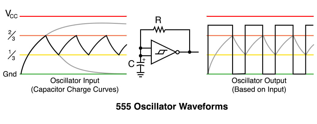
Figure 5. 555 oscillator with hysteresis waveforms.
In this figure, you can also see why an asymmetrical square wave output is created. The first pulse generated by the oscillator is a bit longer than the rest as the capacitor charges from the ground.
Related Content
Learn more about the fundamentals behind this project in the resources below
Textbook:
Industry Article:
Worksheets:
Calculators:
- 555 Timer Astable Oscillator Circuit Calculator
- Comparator With Hysteresis (Schmitt Trigger) Calculator