Facebook
 Google
 GitHub
 Linkedin
555 Lab - Blue LED Flasher With Voltage Doubler
Project Overview
The circuit of Figure 1 used in this project adds a voltage doubler feature to the circuit and concepts from these two experiments:
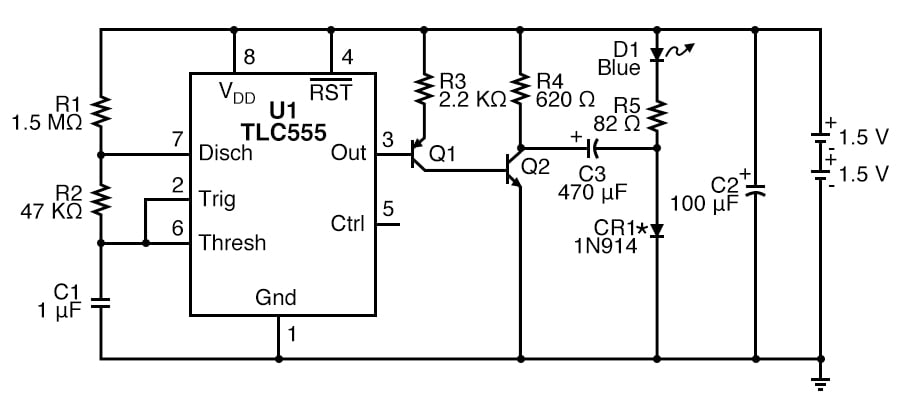
Figure 1. Schematic diagram of the 555 timer LED flasher with high voltage LED drive.
Blue and white light-emitting diodes (LEDs) have a higher Vf (forward dropping voltage) than other colors, typically around 3.6 V. Therefore, 3 V batteries can’t drive them without help. Thus, the need for extra circuitry will be added to this experiment.
The capacitor, C3, is used to double the voltage of this pulse across the blue LED, but it can only do this for a short time. Measuring the current through the LED is impractical with this circuit because of the short pulse duration.
Parts and Materials
- Two AAA batteries
- Battery clip
- U1 - complementary metal-oxide semiconductor (CMOS) TLC555 timer IC (or equivalent).
- Note: This is a static-sensitive part. If you do not use protection as described in the electrostatic discharge (ESD) chapter, you run the risk of destroying it.
- Q1 - 2N3906 PNP transistor or equivalent
- Q2 - 2N2222 NPN transistor or equivalent
- CR1 - 1N914 diode or equivalent
- D1 - Blue LED
- R1 - 1.5 MΩ 1/4W 5% resistor
- R2 - 47 kΩ 1/4W 5% resistor
- R3 - 2.2 kΩ 1/4W 5% resistor
- R4 - 620 Ω 1/4W 5% resistor
- R5 - 82 Ω 1/4W 5% resistor
- C1 - 1 µF tantalum capacitor
- C2 - 100 µF electrolytic capacitor
- C3 - 470 µF electrolytic capacitor
Learning Objectives
- Learn a practical application for an RC time constant
- Learn one of several 555 timer astable multivibrator configurations
- Working knowledge of duty cycle
- How to handle ESD-sensitive parts
- How to use transistors to improve current gain
- How to use a capacitor to double voltage with a switch
Instructions
Step 1: Build the 555 oscillator circuit shown in Figures 1 and 2.
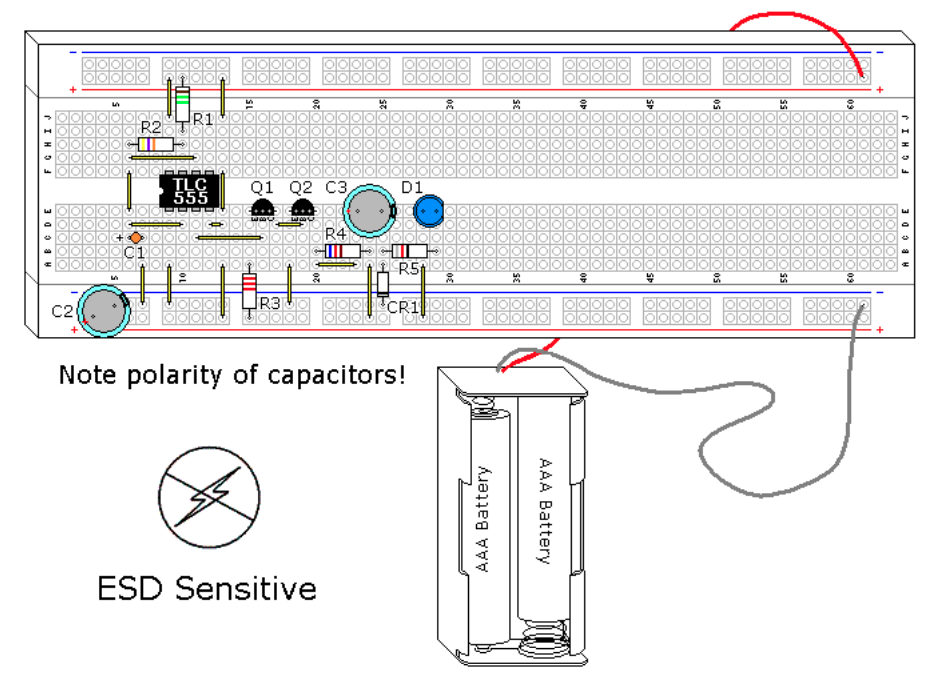
Figure 2. Breadboard implementation of the 555 timer LED flasher with high voltage LED drive.
The LED should flash approximately every 1 second. As in the previous circuits, the LED is given a 0.03-second (30 ms) pulse.
Step 2 (optional): This particular design can also be used with a single 1.5 V battery. If you want to try a 1.5 V battery, change R5 to 10 Ω and use a red LED with a better CR1 diode. CR1 is not the best choice for this component, it was selected because it is a common part and it works. Almost any diode will work in this application.
Schottky and germanium diodes drop much less voltage than silicon diodes. A silicon diode drops 0.6-0.7 V, while a Schottky diode drops 0.1-0.2 V, and a germanium diode drops 0.2 V-0.3 V. If Schottky or germanium diodes are used, the reduced voltage drop would translate into a higher voltage across the LED and increased intensity, as the circuit's efficiency is increased.
Voltage Doubler Theory of Operation
In this circuit, Q2 is used as a switch. When Q2 is off, C3 is charged to the battery voltage minus the diode voltage drop of CR1, as shown in Figure 3.
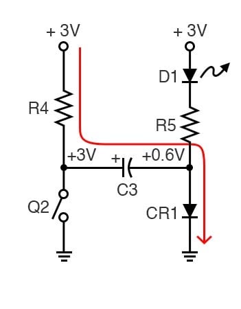
Figure 3. When transistor switch Q2 is open, capacitor C3 charges.
Since the forward voltage (Vf) of a blue LED is 3.4 to 3.6 V, it is not conducting and is effectively out of the circuit.
Figure 4 illustrates what happens when Q2 turns on.
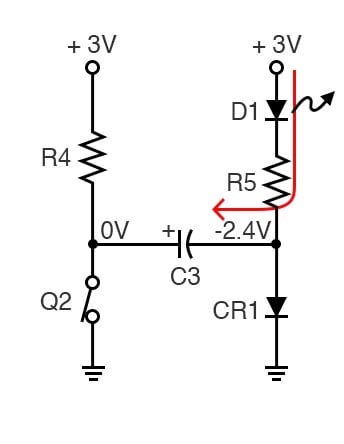
Figure 4. When transistor switch Q2 is closed, the voltage across the diode doubles, turning it on
The capacitor C3's positive (+) side is grounded, which moves the negative (-) side to -2.4 V. The diode CR1 is now reverse-biased and is effectively out of the circuit. The -2.4 V is discharged through R5 and D1 to the +3.0 V of the batteries. The total of 5.4 V provides enough voltage to light the blue LED. The 5.4 V value is not quite double the supply voltage because of the loss of diode CR1. Long before C3 is discharged, the circuit switches back, and C3 starts charging again.
You may notice a dim blue glow in the blue LED even when it is off. This demonstrates the difference between theory and practice, 3 V is enough to cause some leakage through the blue LED, even though it is not fully conducting. If you were to measure this current, it would be very small.
Related Content
Learn more about the fundamentals behind this project in the resources below.
Textbook:
- Multivibrators
- Voltage and Current Calculations
- Solving for Unknown Time
- Electrostatic Discharge
- Bipolar Junction Transistors
Calculator:
Projects:
Worksheet: