 Facebook
 Google
 GitHub
 Linkedin
Fast, Ultrafast, Soft, Standard, Schottky: Selecting the Right Rectifier
This article is a deeper dive into the speed-related recovery characteristics of rectifiers, and how this dynamic behavior has significant effects on the circuits in which the rectifier is placed.
This is Part 2 of the two-part article series covering the different types of power rectifiers, their static and dynamic characteristics, and what the circuit designer needs to understand to make appropriate selections. This second article is a deeper dive into the speed-related recovery characteristics of rectifiers, and how this dynamic behavior has significant effects on the circuits in which the rectifier is placed.
Introduction
The concept of an ideal diode can deceive the designer into overlooking the importance of specifying the correct power rectifier to meet his/her circuit designs' performance requirements. Far from being simple “one-way valves for current,” real-world rectifiers present an array of circuit-affecting characteristic parameters.
In this two-part article series, we are exploring how these parameters both define the types of rectifiers and drive the development of rectifier technology. Along the way, we will gain the understanding necessary to choose wisely for our design projects.
Here in part two, we explore the dynamic behavior defining “soft” recovery and “forward” recovery, then we compare the dynamic behavior of Schottky barrier vs. PN junction rectifiers. We'll also take a quick look at the progress of rectifier technology over the last century.
Before continuing, please read the first part of the series here: Fast, Ultrafast, Standard, Soft, Schottky: What’s the Right Rectifier for Your Power Circuitry?
Going Fast or Ultrafast—How Do You Slow Down?
In part one of this article series, we reviewed the static (steady-state) parameters important for rectifiers and then discussed the key defining dynamic parameter of rectifiers: trr. We learned how trr specifies how quickly rectifiers stop conducting the moment they are switched from high forward current operation to a reverse-biased condition. We learned that this reverse recovery parameter, trr, is what defines a rectifier as fast, ultrafast, or standard recovery.
Now we are going to learn that it is not only the speed of recovery that is important, but also how abruptly we put on the brakes.
Soft? What Does Soft Recovery Mean?
From the first half of this article, you have gained an understanding of what reverse recovery is, and why recovery speed is important. But what do we mean by “soft” recovery?
According to JEDEC Standard No. JESD282B.01, power rectifiers “can possess either of two types of recovery characteristics. After the reverse current reaches its peak value … it may immediately or a short time later decrease very abruptly (abrupt recovery) or it may decrease slowly and smoothly to its steady-state reverse blocking value (soft recovery).”
To gain a more intuitive understanding of what we mean by “soft recovery” and why it's important, let's explore a rough analogy with velocity (v) substituting for current (I). Suppose you were considering a bungee jump from a structure 500 feet above the ground, and further suppose that you were offered two choices to arrest your plummet towards the earth: a 100-foot length of stiff rope or a 100-foot length of appropriately elastic bungee cord. Both will prevent your body from hitting the ground.
However, choosing the inelastic rope would, of course, result in a disastrous and probably fatal outcome due to the very high dv/dt change in your velocity as the rope suddenly becomes taut at the end of your fall. You would choose the elastic bungee, of course, as this would present a return to zero velocity at a dv/dt more likely to be survivable.
Just as high dv/dt deceleration can damage physical systems via impact forces (because Force = m(dv/dt)), high dI/dt currents can cause high voltage spikes in circuits having inductance, because Voltage = L(dI/dt). (And any real-world circuit will have some inductance, even if it's only parasitic inductance.)
Let's revisit our JEDEC trr waveform and compare a soft recovery to an abrupt recovery:

Soft vs. abrupt recovery waveforms (image adapted and redrawn from JEDEC Standard No. JESD282B.01, Figure 6.1)
At first glance, we might be tempted to think that we could define the “softness” of our recovery characteristic as a simple ratio of trrr to trrf. We can see that this ratio would be small for the soft diode (e.g., ~1/3 or ~0.33) and large (e.g., ~3/1 or ~3) for the abrupt diode in these two example waveforms. To be sure, compressing the time for the current to recover from Irm will necessarily make it more abrupt, all other things being held constant.
But let's take a look at two more reverse recovery waveforms, these both having a trrr/trrf ratio closely matching that of our soft recovery example:

Two more examples of abrupt recovery waveforms (image adapted from JEDEC Standard No. JESD282B.01, Figure 6.1)
You can see from these last two waveforms that a simple trrr/trrf ratio would be missing the key physics point: it's the slope of the curve, the dI/dt, that's crucial!
The JEDEC standard, therefore, defines a reverse recovery softness factor (RRSF) for rectifiers as the ratio of the “maximum absolute magnitude of dI/dt within the trrr region to that in the trrf region.”
To stretch the bungee analogy a little further (no pun intended), some manufacturers term this ratio the “snap factor,” and values considered “soft” for ultrafast rectifiers would typically be represented by numbers larger than 0.5 (i.e., 1/2).
When reviewing rectifier datasheets, be aware that trrr and trrf are frequently annotated as “ta” and “tb,” respectively; and even though this is obsolete notation, it is still found in many recent datasheets.
Forward Recovery
Back at the beginning, we said there were two types of recovery. We've discussed reverse recovery at some length, but let's not forget to talk about the other type: forward recovery.
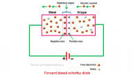
Returning to the concept of the theoretically ideal diode, such a device would, of course, conduct current without any resistance or forward voltage drop the very instant that the anode becomes positive with respect to the cathode. However, as with reverse recovery, there is a finite amount of time required for the PN junction to establish itself in the opposite biased condition. The external electric field must have time to inject carriers into the depletion zone (bringing the junction into the forward-biased condition).
Forward recovery is defined as the time required for voltage across the diode to reach a defined level, close to its steady-state VF value, when an abrupt forward current pulse is applied. Until the diode has reached the end of the forward recovery time, tfr, the voltage drop may briefly climb to VFRM, a value many times its steady-state VF value.
The figure below has been adapted and redrawn from JEDEC Standard No. JESD282B.01, Figure 5.13.

JEDEC forward recovery waveform
But for forward recovery to be a concern, the circuit in which the rectifier must perform would have to present dI/dt of at least tens of amps per microsecond. Nevertheless, there are applications where this is the case—freewheeling diodes (aka flyback diodes, clamping diodes, snubbers) being notable examples.
The Schottky Rectifier
At this point, we need to discuss the recovery characteristics of the Schottky rectifier. In simplest terms, there are none! At least not if we define reverse recovery as the time it takes for the junction to be cleared of charge carriers—and the depletion zone re-established and expanded.
Up to now, we have been discussing the recovery characteristics of the silicon PN junction rectifier. These recovery characteristics are due to the physics of the PN semiconductor junction. The Schottky rectifier behavior, however, is not based on the PN junction. Rather, its ability to rectify is based on the Schottky barrier junction (sometimes known as a metal-on-silicon junction).
Unlike the PN junction, the Schottky junction does not have a depletion zone. Schottky rectifiers, therefore, can have typical trr values of 10ns or less for some modest-current devices. With Schottky rectifiers, the switching can essentially be considered instantaneous, with the only delay being from the junction capacitance (which is typically small). And since the small amount of recovery time they have is primarily due to capacitance, that recovery is soft as well as fast.
Limitations of Schottky Rectifiers
So if Schottky rectifiers are so uber fast and soft and low VF, why aren't they always the best choice? Well the answer, unfortunately, is that they are prone to self-destruction via thermal runaway if the power dissipation, heat-sinking, and operating temperature conditions are not properly taken into account. This is because their reverse leakage increases exponentially with temperature.
For example, a typical Schottky that has an Ir of 0.25mA at 25°C will have that leakage balloon to 30mA at 125°C—that's more than a factor-of-100 increase!
Nevertheless, a Schottky may be a good choice under the following conditions:
- if your VR requirement is modest (i.e., only low voltages expected in the circuit)
- if you can tolerate some substantial leakage (and the heat that the VR × Ir product will create)
- if you are confident that you can sink away the heat adequately to maintain a low operating temperature under all foreseeable conditions
Comparison of Key Parameters
Some are faster, some are soft, and some are cheap, while others may be dear. What we need to organize our thoughts and put away our fear; What we need right now I think, is a table right about here. (My apologies for the loose, inverted iambic pentameter verse, but this table merits a special introduction.)
We have presented here, in matrix form, the key differentiating parameters (given as typical values and typical ranges) for commonly available one-amp rectifiers in the categories we have discussed.

Key Parameters for Different Rectifier Types (Typical Values/Ranges)
Rectifier Technology History
Before we finish up discussing how to choose the right power rectifier, I think it would be elucidating to examine the choices available to prior generations of engineers and circuit designers. The chart below provides a high-level overview of the last century of technological advancement in power rectifiers.
Note: For this purpose, we will narrowly define rectifiers as “power diodes” and ignore late-19th-century mechanical means of rectification such as resonant reed vibrators, synchronous motor-driven contacts, and motor-generators. Likewise, we will ignore modern circuit techniques like synchronous rectification where MOSFETs replace rectifiers.
These caveats in place, the chart below plots relative efficiency (in %) and relative physical volume (in cm2) on the vertical axis versus technology and the applicable decades in use on the horizontal axis. The scale has been normalized for devices capable of 100W power delivered to the load.

Rectifiers of the 20th century
We start our chart at the beginning of the 20th century with electrolytic rectifiers. Although electrolytic rectifiers were commercially produced and readily available in the early 1900s, home-built DIY versions were commonly found in the ham shacks of amateur radio operators, and other enterprising electricity enthusiasts. They were easily and economically constructed by mixing borax (sodium tetraborate) into a pint jar of water and submerging an aluminum plate and a lead plate into the electrolyte on opposite sides of the jar.
During the first few minutes of running an AC current between the two electrodes, a forming process takes place in which the aluminum electrode reacts with the solution to achieve a thin surface coating that only permits current to flow in one direction and thus provides the rectifying action. (The lead electrode does not form a coating. It simply provides a connection to the electrolyte.) The efficiency of these electrolytic rectifiers was actually greater than the vacuum tube rectifiers that eventually supplanted them.
Vacuum tube rectifiers were a little smaller in volume and were not prone to spilling or leaking liquids. Vacuum tube rectifiers were common in most consumer electronics through the first half of the 20th century, and indeed they still have some aficionados among hardcore audiophiles today.
Copper oxide and selenium oxide rectifiers became a commercial alternative to vacuum tube rectifiers and were often selected by designers for their compact size and mechanical ruggedness, as well as their increased efficiency. They were, however, subject to degradation over time and produced a distinctive foul and pungent odor when failing.
Semiconductor rectifiers (first germanium, then silicon and Schottky) became the mainstay for commercial, industrial, and automotive applications throughout the second half of the 20th century, and they are still the design engineer's go-to set of parts today.
Conclusion
You should now have an understanding of how switching speed, circuit dI/dt, and diode behavior under both static and dynamic operating conditions will drive your rectifier selection. Remember, you'll always need to start by defining the maximum sustained forward current, IO, that your rectifier will have to support, as well as the sustained reverse blocking voltage VR.
Armed with that information and an understanding of rectifier recovery characteristics, you'll be prepared to dive into the various manufacturers' datasheets, compare and contrast, and make your choices.
Not that you'll need it now, but here's a bullet list to provide a starting point when choosing the type of power rectifiers best suited for use in your next high-power design.
- High-voltage switch-mode power supplies (SMPS): Use fast and ultrafast rectifiers with low trr.
- Low-voltage SMPS: Use Schottky rectifiers.
- Relay and solenoid coil clamping and snubber circuits: Use fast rectifiers with low tfr.
- Freewheeling diode circuits: Use ultrafast rectifiers with low tfr and low trr.
- Current steering, supply OR-ing, and reverse polarity protection: Use standard recovery rectifiers for high-voltage applications and Schottky for low-voltage applications.
- AC mains 50/60 Hz applications: Use standard recovery rectifiers.
- Automotive, wind turbine, microhydro, and other 3-phase alternators: Use standard recovery rectifiers.
Keep an eye out for upcoming articles on related topics (such as silicon controlled rectifiers (SCR), triacs, and other power thyristors).
Related Content


Congratulations upon your treatment of this vital (albeit, IMO, largely underappreciated) subject! 😊
Most sincerely
HP
Could you please define the difference between a “freewheeling diode circuit” and a snubber/ clamp diode? All my Internet searches seem to define freewheeling as synonymous with snubber/clamp. I get that snubber/clamp/catch/flyback diodes are for shorting back-EMF from an inductor, but how does a “freewheeling” diode circuit differ?