Facebook
 Google
 GitHub
 Linkedin
555 Lab - Monostable Multivibrator (One-shot)
Project Overview
The monostable multivibrator, or one-shot, is one of the most basic 555 circuits. This circuit (Figure 1) is part of the typical 555 datasheets, complete with the math needed to design to specification, and is one of the reasons a 555 is referred to as a timer.
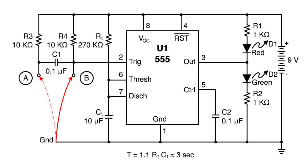
Figure 1. Schematic diagram of the 555 one-shot timer with LED output indicators.
As illustrated in Figure 2, at the falling edge of the trigger, the output goes high. It will stay high for the full time period, T.
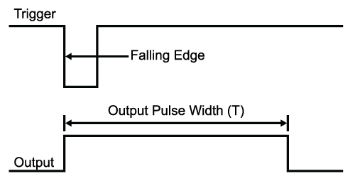
Figure 2. Trigger and output waveforms for a one-shot timer (monostable multivibrator).
Parts and Materials
- One 9 V battery
- Battery clip
- Mini-hook clips
- A watch with a second hand/display or a stopwatch
- A wire, 11/2” to 2” (3.8 mm to 5 mm) long, folded in half (shown as red wire in the illustration)
- U1 - 555 timer IC
- D1 - Red light-emitting diode (LED)
- D2 - Green LED
- R1, R2 - 1 kΩ 1/4 W resistors
- Rt - 27 kΩ 1/4W resistor
- Rt - 270 kΩ 1/4W resistor
- C1, C2 - 0.1 µF capacitor
- Ct - 10 µF capacitor
- Ct - 100 µF capacitor
Learning Objectives
- Learn how a monostable multivibrator works
- Learn a practical application for an RC time constant
- How to use the 555 timer as a monostable multivibrator
Instructions
Step 1: Build the circuit illustrated in the schematic diagram of Figure 1 and the breadboard implementation of Figure 3.
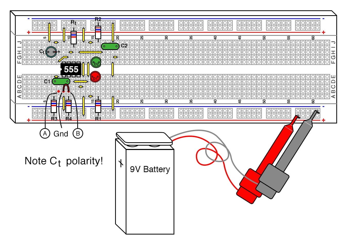
Figure 3. Breadboard implementation of the 555 one-shot timer with LED output indicators.
Step 2: Verify that the green LED lights are when the 555 output is high (i.e., switched to VCC) and the red LED lights when the 555 output is low (switched to ground).
This particular monostable multivibrator (also known as a one-shot timer) is not a re-triggerable type. This means that once triggered, it will ignore further inputs during a timing cycle, with one exception, which will be discussed below.
Step 3: The timer starts when the input goes low or switches to the ground level and the output goes high. You can prove this by connecting the red wire shown in Figure 1 between the ground and point B, disconnecting it, and reconnecting it.
Step 4: It is an illegal condition for the input to stay low for this design past timeout. For this reason, R3 and C1 were added to create a signal conditioner, which will allow edge-only triggering and prevent illegal input. You can prove this by connecting the red wire between the ground and point A. The timer will start when the wire is inserted into the protoboard between these two points and ignore further contacts.
Step 5: If you force the timer input to stay low past timeout, the output will stay high even though the timer has finished. As soon as this ground is removed, the timer will go low.
Step 6: Rt and Ct were selected for 3 seconds timing duration. You can verify this with a watch, 3 seconds is long enough that we slow humans can actually measure it. The resistor and capacitor are probably 5% and 20% tolerance, respectively, so the calculated times you measure can vary as much as 25%, though it will usually be much closer.
Step 7: Try changing Rt from a 270 kΩ to a 27 kΩ resistor and Ct from a 10 µF to a 100 µF capacitor. Since the RC time constant is the same, there should be no difference in how it operates.
Step 8: Next, try replacing Rt with the 270 kΩ resistor. Since the RC time constant is now 10 times greater, you should get close to 30 seconds.
Another nice feature of the 555 is its immunity from the power supply voltage. If you were to swap the 9V battery with a 6V or 12 battery, you should get identical results, though the LED light intensity will change.
C2 isn’t actually necessary. The 555 IC has this option in case the timer is being used in an environment where the power supply line is noisy.
You can remove it and not notice a difference. The 555 itself is a source of noise since there is a very brief period of time that the transistors on both sides of the output are both conducting, creating a power surge (measured in nanoseconds) from the power supply.
Theory of Operation
Figure 4 is the starting and ending point for this circuit, where the output is low and it is waiting for a trigger to start a timing cycle. Looking at the functional schematic shown in Figure 4, you can see that pin 7 (discharge) is connected to a transistor going to the ground.
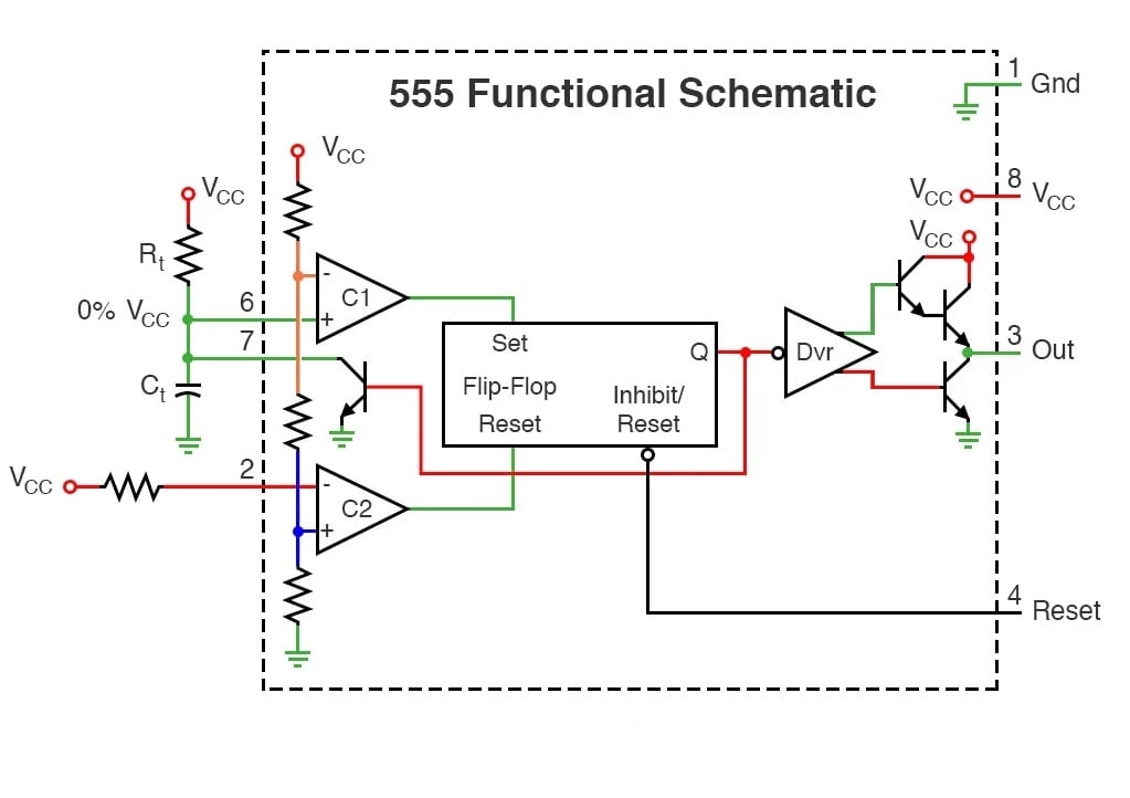
Figure 4. The stable state of the 555 timer one-shot waiting for a trigger input.
This transistor is simply a switch. When the flip-flop output Q is high, as indicated by the red lines in the figure, the transistor is on and connects the capacitor Ct to the ground. Figure 5 shows what happens when the 555 receives a trigger, starting the sequence.
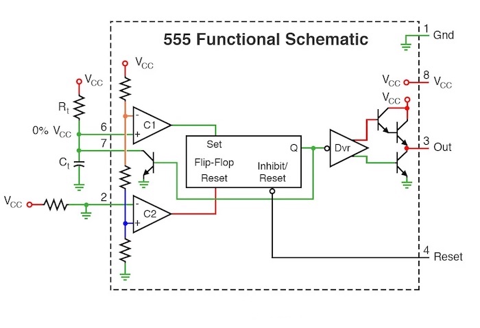
Figure 5. Triggering the 555 timer one-shot by grounding pin 2 (trigger).
Pin 2 (trigger) is forced low, which causes comparator C2 output to go high. This resets the flip-flop output Q low, which turns off the transistor connected to pin 7 and the capacitor Ct.
The capacitor Ct now begins charging through resistor Rt as illustrated in Figure 6.
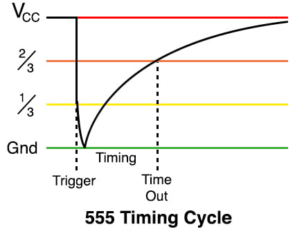
Figure 6. Capacitor voltage during a 555 one-shot timing sequence.
The red line represents the power supply voltage, VCC, and the green line represents the ground (0 volts). The capacitor Ct charges up from the ground towards VCC following an RC exponential charging curve. Note: it will not reach VCC due to the operation of the circuit.
Figure 7 shows the state of the circuit while the capacitor is charging.
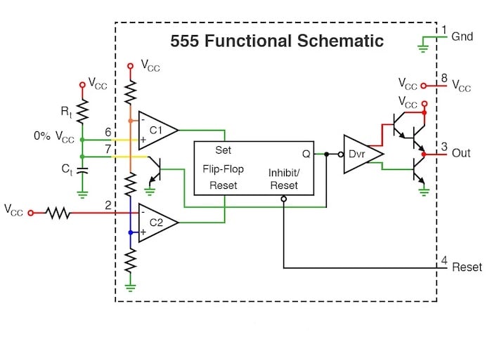
Figure 7. State of the 555 timer one-shot while the capacitor is charging.
During this time, the circuit is in a stable configuration, and the output is high.
Figure 8 shows the circuit in the middle of switching off when it hits timeout.
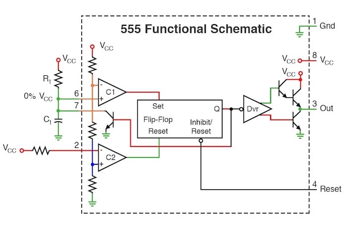
Figure 8. When the capacitor voltage reaches 2/3 VCC and sets the flip-flop.
Capacitor Ct has charged to 2/3 VCC. This forces comparator C1 to switch high and set the flip-flop. The flip-flop output Q goes high, which will turn on the discharge transistor at pin 7. This also resets the output low.
At this point, the pin 7 transistor is on, keeping the capacitor Ct discharged. The circuit is now in the state illustrated in Figure 9, which is identical to the starting state of Figure 4.
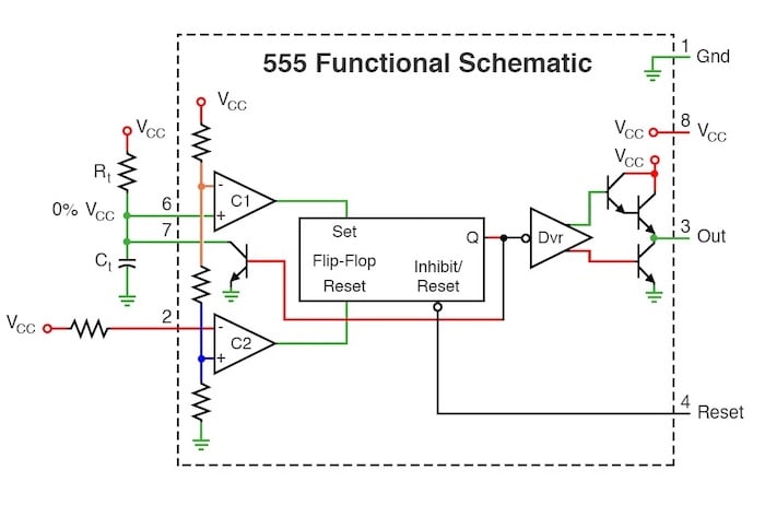
Figure 9. Return to the stable state of the 555 timer one-shot.
Related Content
Learn more about the fundamentals behind this project in the resources below.
Textbook:
- Electric Fields and Capacitance
- Capacitors and Calculus
- Voltage and Current Calculations
- Solving for an Unknown Time
- Monostable Multivibrators
Calculator:
Worksheets: