 Facebook
 Google
 GitHub
 Linkedin
Introduction to the Conversion of Flip-Flops
This article describes the steps necessary to convert a given flip-flop into a desired flip-flop using the example of an SR-to-JK flip-flop conversion.
This article describes the steps necessary to convert a given flip-flop into a desired flip-flop using the example of an SR-to-JK flip-flop conversion.
Introduction
Flip-flops are bi-stable single-bit memory devices which are one among the numerous digital components used in sequential systems.
The various kinds of flip-flops in existence are SR flip-flop, JK flip-flop, D flip-flop, and T flip-flop. Each of them exhibit unique characteristics and hence result in different output for the same combination of input states. Hence, whenever we want one flip-flop to mimic the behaviour of the other, we need to resort to a flip-flop conversion technique.
Creating an Excitation Table
The output of a flip-flop at a given instant depends on both its input(s) as well as its present-state, defined by the information summarized and presented by its truth table. In other words, in the truth table of a flip-flop, the next-state output will be the last column. That column is determined by the combination of bits in its preceding columns, which will be the input(s) followed by its present-state.
Now, just imagine that we want to know the sequence of the input combination which results in a definite output state. The information pertaining to this can be obtained by back-tracing (in terms of columns) the information presented by the truth table of the flip-flop. That is, we will have the first two columns as the present- and the next-states of the flip-flop which will be followed by the column(s) representing the flip-flop inputs.
Such a table can be aptly referred to as an "excitation table" as it indicates the excitations to be provided at the input pins of the flip-flop to result in the expected outcome for a known present-state.
The concept explained can be further made clear by the following example, where we obtain the excitation table for the SR flip-flop from its truth table:
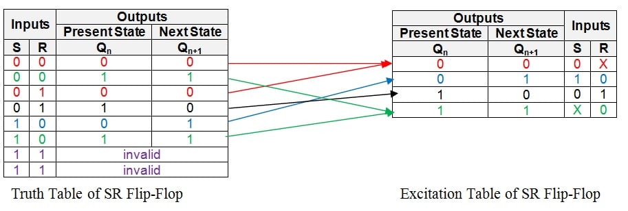
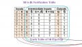
Figure 1: Truth table and excitation table of an SR flip-flop
The first row in the truth table above shows that the present- and the next-states of the flip-flop will be 0 and 0 if its inputs are S = 0 and R = 0.
The same output combination also appears even when the inputs are given as S = 0 and R = 1 as evident from the third row of the truth table. This indicates that, in order to obtain the SR flip-flop's output as 0, we must drive the input pin, S, to low (i.e. S = 0) while the other input, R, may be pulled either low or high (i.e. R = 0 or 1), provided its present state is 0. In other words, the input combination S = 0 and R = X (Don't Care) results in the next-state of the flip-flop to be 0 from its current state, which is equal to 0.
Now, note that the same information is successfully conveyed by the entries (shown in the red colour) in the first row of the excitation table.
Similarly, the present-state and next-state combination of 0 and 1 is obtained for the SR flip-flop when its inputs are S = 1 and R = 0. This information is concisely represented by the second row of the excitation table (shown in the blue colour).
Following on the same grounds, we find that to obtain present- and next-states of the flip-flop as 1 and 0, we should have S = 0 and R = 1, as indicated by the entries in the black colour corresponding to the third row of the excitation table.
Lastly, note that S can be either 1 or 0 (i.e. S = X) and R should be 0 in order to obtain the present- and next-states of the flip-flop as 1 and 1. This is shown by the green colour entries in the fourth row of its excitation table.
Having done this, all the information present in the truth table is transferred appropriately into the excitation table, completing it.
By employing the same procedure, the excitation tables can be obtained for all other types of flip-flops viz., JK flip-flop, D flip-flop, and T flip-flop as shown by Figures 2, 3 and 4, respectively:
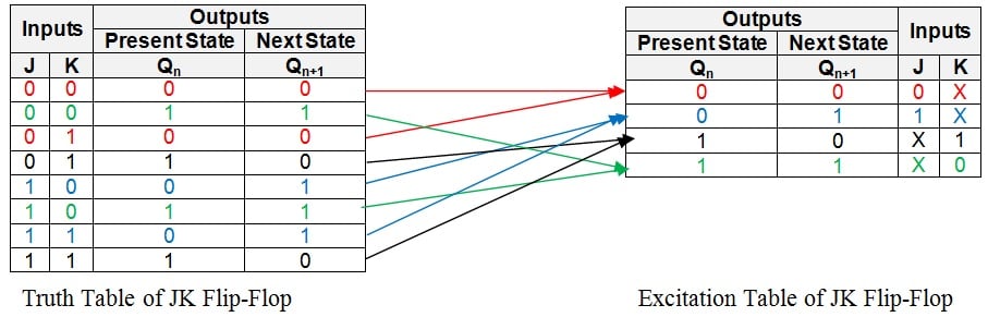
Figure 2: Truth table and excitation table of a JK flip-flop
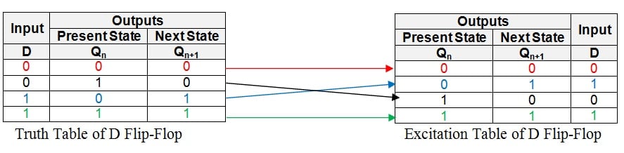
Figure 3: Truth table and excitation table of a D flip-flop
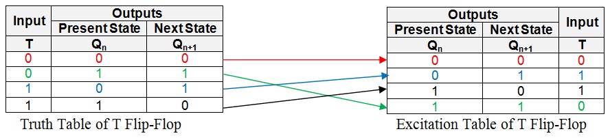
Figure 4: Truth table and excitation table of a T flip-flop
Meaning of "Desiring a Flip-Flop"
When we say, "We want a particular flip-flop", it means that we are clear about the flip-flop outcomes for the given combination of inputs for each case of its present-state. That is, we have the truth-table information of the desired flip-flop in our hands. However, the expected outcome cannot be obtained directly from the given flip-flop as its behaviour for the same combination of input states and the present-state will be different (most of the time).
Hence, one needs to determine the sequence of the input bits in the given flip-flop which results in the same output (for a definite present-state) as that in the case of the desired flip-flop. As mentioned before, this information is readily present in the form of the entries in the excitation table of the given flip-flop.
Knowing this, the next step would be to merge the information presented by the excitation table of the given flip-flop with the information present in the truth table of the desired flip-flop. This can be done by filling the entries from the excitation table of the given flip-flop into the appropriate rows of the truth table corresponding to the desired flip-flop by adding additional column(s) which represent the input(s) of the given flip-flop. When done so, we will get a new table which we can refer to as a "Conversion Table":
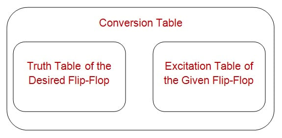
Figure 5: Structure of a conversion table
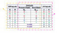
For example, the conversion process of the SR flip-flop into a JK flip-flop is initiated by writing the truth table for the JK flip-flop as shown by the yellowish enclosure in Figure 6. Here, it is seen that the first row has the present- and the next-states of the flip-flop as 0 and 0 (the red entries in the truth table).
Now we look at the excitation table of the SR flip-flop (shown in the right-side of Figure 6) which has a row indicating the present- and the next-states of the SR flip-flop to be 0 and 0. As seen by the red entries in the excitation table, this corresponds to the first row for which the inputs are S = 0 and R = X.
The same information is placed into the first row of the JK flip-flop's truth table by adding two more columns, S and R (as shown by the pink enclosure in Figure 6), to result in an SR-to-JK Conversion Table:
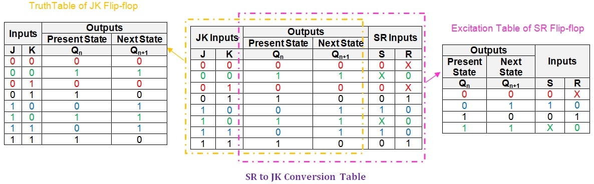
Figure 6: SR to JK conversion table
Similarly, the second row of the JK flip-flop has the present- and the next-states as 1 and 1 which correspond to the fourth row of the SR flip-flop's excitation table (shown as the green entries in the respective tables). The values for the S and R inputs corresponding to this output combination is seen to be X and 0, respectively, which are filled into the second row of the conversion table (shown in green again).
By following the same procedure for each and every row, the entire table can be filled to obtain a completed SR-to-JK flip-flop conversion table, as shown in the center of Figure 6.
Using a K-Map to Obtain Logical Expressions
Having obtained the conversion table, the next step is to arrive at the logical expressions for the inputs of the given flip-flop in terms of the inputs of the desired flip-flop and the present-state.
Further, you should take care to obtain the minimal logical expression so as to facilitate the design of the circuit with the least possible gates. This objective can be achieved by employing any of the suitable Boolean algebraic simplification techniques like that of the K-map technique.
According to this, for the example under consideration, we need to obtain the expressions for the inputs S and R in terms of J, K, and Qn. This can be done by employing the K-map simplification technique as shown in Figure 7:
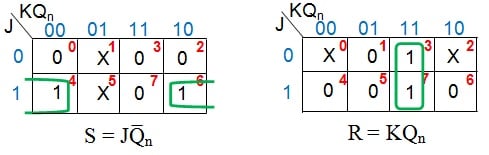
Figure 7: K-map simplification for the inputs of the SR flip-flop in terms of J, K, and Qn
This results in the expression for S input as JQ̅n and for R input as KQn.
An SR-to-JK Flip-Flop Conversion
At last, by using the information provided by the logical expression obtained, we can re-design the connections to be provided at the input pins of the given flip-flop. This can be achieved either by just manipulating the connections and/or by adding additional combinational circuit(s), inorder to make the given flip-flop functionally equivalent to the desired flip-flop.
In the example provided, the logical expressions obtained for S and R indicate two things:
- The input pin S of the SR flip-flop is to be fed by the output of a two-input AND gate which is driven by J and Q̅n.
- The input pin R of the SR flip-flop is to be fed by the output of a two-input AND gate which is driven by K and Qn.
Both of these must be satisfied in order to make an SR flip-flop behave like a JK flip-flop as shown in Figure 8:
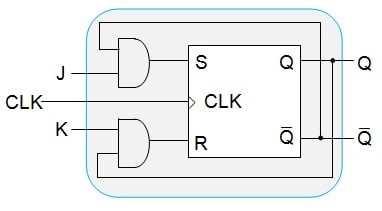
Figure 8: An SR flip-flop behaving like a JK flip-flop
In Review
In this article, we have presented a detailed procedure which can be carried out to convert any of the given flip-flops into any other type of flip-flop. We have shown this using an example wherein an SR flip-flop is made functionally equivalent to JK flip-flop.
However, it is to be noted that similar steps will also hold good for mutual conversion between any kind of flip-flops available. We can also cross-verify whether the conversion process was successful or not. These things will be covered in Part 2 of this article.
Next Article in Series: Conversion of Flip-Flops — Part II
Related Content


Thanks a lot…
Nice presentation. Thanks.