Facebook
 Google
 GitHub
 Linkedin
Conversion of JK Flip-Flops
This article teaches you how to convert a given JK flip-flop circuit to other types of flip-flops while verifying the process of conversion.
This article teaches you how to convert a given JK flip-flop circuit to other types of flip-flops while verifying the process of conversion.
Previous Articles in This Series
A Quick Review
The previous two parts of this series discussed the method of conversion and verification processes for (i) SR-to-JK flip-flop, (ii) SR-to-D flip-flop and (iii) SR-to-T flip-flop. Continuing it, here, we apply the same techniques for converting the given JK flip-flop to SR-, D- and T-types, while verifying the conversion. Please read Part I and Part II before continuing.
Conversion of a JK-to-SR Flip-Flop
Step 1: Write the JK-to-SR conversion table
The first step in converting a JK-to-SR flip-flop would be to write a JK-to-SR conversion table as shown in Figure 1.
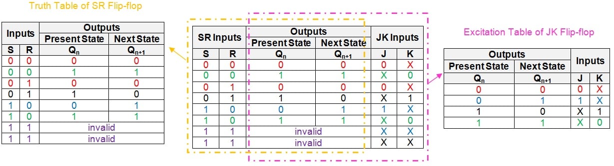
Figure 1: JK-to-SR conversion table. Click to enlarge.
The intention behind this step is to represent the information presented by the truth table of the SR flip-flop and the excitation table of the JK flip-flop in a common table.
However, note that the last two rows of the table have "don't cares" as the entries in their J and K columns. This is because the input combination of S = 1 and R = 1 is invalid in the case of an SR flip-flop.
Step 2: Simplify the logical expressions for the inputs
Now, simplify the logical expressions for the inputs of the given flip-flop (J and K) in terms of the inputs of the desired flip-flop (S and R) and the flip-flop's present-state, Qn.
This can be done by following any logical simplification technique like that of the K-map. (For reference, I have covered in a previous article how to use the K-map method of simplification.)
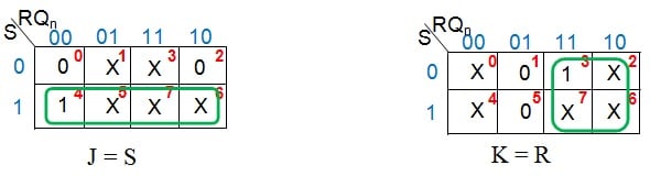
Figure 2: K-map simplification for J and K inputs in terms of S, R and Qn
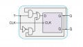
Figure 2 shows that the given JK flip-flop behaves readily as an SR flip-flop—it needs neither additional circuitry nor the manipulation of the connections. So the required digital system (Figure 3) will be nothing but the given JK flip-flop.
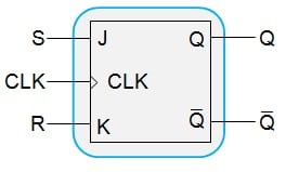
Figure 3: A JK flip-flop behaving as an SR flip-flop
Step 3: Verification
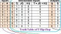
The next step is to verify our design using a JK-to-SR verification table as shown in Figure 4. The approach employed is simple: write the truth table for the designed system and compare it with the truth table of the desired flip-flop.
.jpg)
Figure 4: Comparison between the JK-to-SR verification table and the truth table of an SR flip-flop. Click to enlarge.
From the figure, it is evident that the entries in the first, second, third, and seventh columns of the JK-to-SR verification table (shaded in beige) are consistent with the entries found in the truth table of the SR flip-flop. Note that the last two rows of the verification table, which seem to differ, can be considered equivalent. This is because the "invalid" in the truth table of the SR flip-flop signifies that the flip-flop is not supposed to be excited by the inputs S = 1 and R = 1. This can also be interpreted as follows: one cannot be sure of the outcome when both the inputs of the SR flip-flop are driven high. This means that the output can be either high or low; thus, the entries in the last two rows of our verification table are acceptable.
Hence we can conclude that the given JK flip-flop can function also as an SR flip-flop.
Now that we're familiar with the steps required to convert and verify these flip-flops, we'll run through two more examples a little bit more quickly.
Conversion of a JK-to-D Flip-Flop
This conversion process is initiated by writing the JK-to-D conversion table as shown in Figure 5.
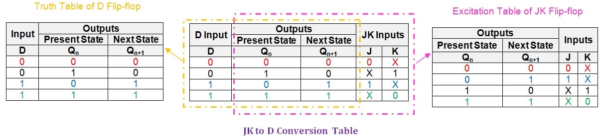
Figure 5: JK-to-D conversion table. Click to enlarge.
Next, let us use a K-map to obtain the logical expressions for the inputs J and K in terms of D and Qn.
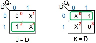
Figure 6: K-map simplification for J and K inputs in terms of D and Qn
From Figure 6, it can be seen that the given JK flip-flop can be converted into a D-type flip-flop by driving its J and K input pins with the D input and its negation, respectively. Thus the additional hardware component required would be a NOT gate, resulting in the digital system shown in Figure 7.
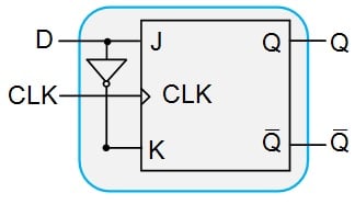
Figure 7: JK flip-flop designed to behave as a D flip-flop
Now, we shall verify our system so as to ensure that it behaves like we expect it to. For this, let us construct the JK-to-D verification table as shown in Figure 8.
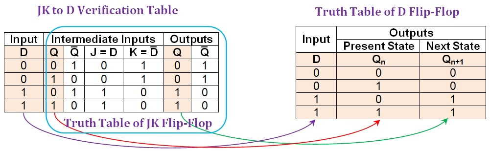
Figure 8: Comparison between the JK-to-D verification table and the truth table of a D flip-flop. Click to enlarge.
From the figure, it can be clearly seen that the entries in the first, second, and sixth columns of the JK-to-D verification table (shaded in beige) are the same as those in the D flip-flop's truth table. Thus, it can be concluded that the conversion process of JK flip-flop into D-type was successful.
Conversion of JK to T Flip-Flop
In order to convert the given JK flip-flop into a T flip-flop, we'll again begin with the initial requirement of obtaining the corresponding conversion table. You can see this table in Figure 9.
.jpg)
Figure 9: JK-to-T conversion table. Click to enlarge.
The next step is to express the inputs of the given JK flip-flop (J and K) in terms of the input of the desired T flip-flop and the present state (T and Qn, respectively).
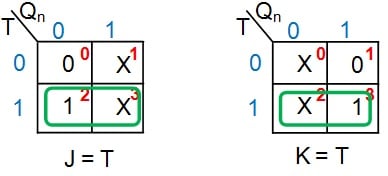
Figure 10: K-map simplification for J and K inputs in terms of T and Qn
Figure 10 shows that in order to convert the given JK flip-flop into a T flip-flop, it's enough just to drive both of its input pins (J and K) with the input T. This results in the digital system shown in Figure 11.
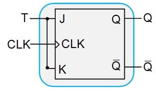
Figure 11: A JK flip-flop designed to behave as a T flip-flop
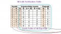
Lastly, verification of the completed conversion process can be performed using the JK-to-T verification table, as shown in Figure 12.
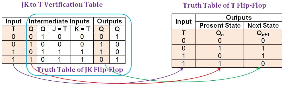
Figure 12: Comparison between the JK-to-T verification table and the truth table of a T flip-flop. Click to enlarge.
Here it can be seen that the first, second, and penultimate columns of the JK-to-T verification table (shaded in beige) are in agreement with the columns of the truth table of the T flip-flop. Hence, the given JK flip-flop functions equivalently to a T flip-flop for any combination of the input and the present state.
Summary
In this article, we have seen the processes associated with converting a JK flip-flop to SR-, D- and T-type flip-flops and then verifying the conversion.
Part IV of this series will discuss converting a given D flip-flop to SR-, JK- and T flip-flops and also present the verifications for these conversions.
Next Article in Series: D Flip-Flops
Related Content