 Facebook
 Google
 GitHub
 Linkedin
SR-to-D and SR-to-T Flip-Flop Conversions
This article will teach you how to verify flip-flop conversions for SR-to-JK flip-flops. It will also guide you through the conversion and verification processes for SR-to-D and SR-to-T flip-flops.
This article will teach you how to verify flip-flop conversions for SR-to-JK flip-flops. It will also guide you through the conversion and verification processes for SR-to-D and SR-to-T flip-flops.
Previous Articles in This Series
In Part I of this article, we discussed the detailed procedure involved in converting an SR flip-flop into a JK flip-flop. Here, we will discuss the method which can be used to verify the conversion process for the same example. We'll also briefly explain the conversion and verification techniques for the conversion of (i) an SR flip-flop into D-type and (ii) an SR flip-flop into T-type.
A Brief Review
In the first part of this article, we had discussed the steps to be followed to convert an SR flip-flop into a JK flip-flop in detail. The process of conversion indicated that, in order to achieve the objective, we would need to do two things:
- Drive the input, S, by the output of a two-input AND gate which has its inputs as J and Q̅n
- Drive the input, R, by the output of a two-input AND gate whose inputs are K and Qn
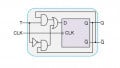
As a result, the digital system designed in Part I is as shown by Figure 1:
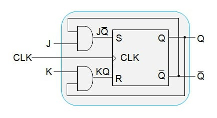
Figure 1: An SR Flip-Flop converted to a JK Flip-Flop
However, we did not verify our design in order to make sure what we obtained is what we needed. Although this would seem to be extra work, it is worth of being done so as to confirm that the system we've designed works as expected.
Verification
As is the case for most digital systems, this design can be verified by exciting it with random inputs and checking whether the outcome will be the same as that of our prediction. This process, when done systematically, will lead to the "truth-table mode of verification" technique.
Anatomy of a Verification Table
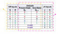
For example, the system shown in Figure 1 can be verified by writing its truth table as shown in Figure 2, which can be referred to as the verification table of an SR-to-JK flip-flop conversion.
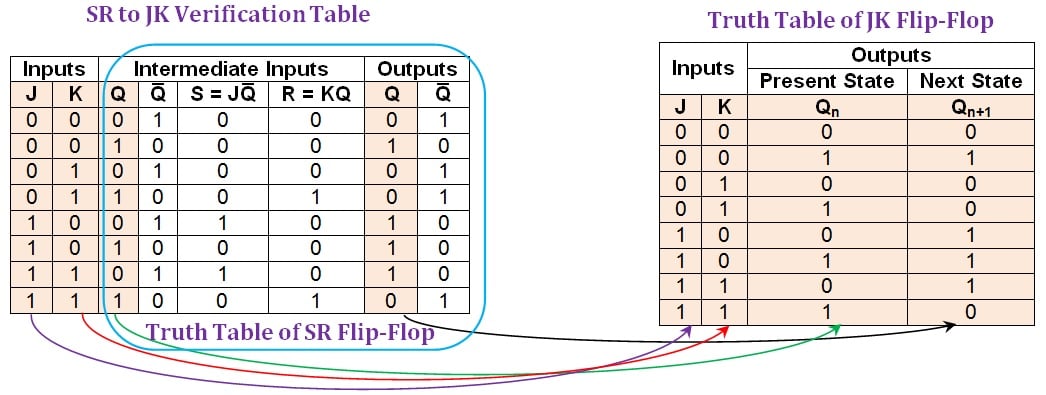
Figure 2: Comparison between an SR-to-JK verification table and the truth table of JK flip-flop. Click to enlarge.
Here, the first two columns designated as "inputs" indicate the input pins which are to be driven by the user (note that these are only the inputs of the desired flip-flop).
The next set of four columns is designated as "intermediate inputs". Among these, the first column (Q) represents the present state of the flip-flop. The next column (Q̅) represents its negation. The following two columns (S=JQ̅ and R=KQ) indicate the bit patterns driving the inputs of the SR (given) flip-flop.
Finally, we have two more columns designated as "outputs" (Q and Q̅) which show the output-bit and its negation for the inputs provided.
Filling Out a Verification Table
First, let us consider the case where the user pulls down both J and K inputs, i.e., J = K = 0.
Now, if the present state of the flip-flop, Q, is 0 (which implies that its inverted bit, Q̅, is 1), then the input pins S and R will be driven by 0 (as S = JQ̅) and 0 (as R = KQ), respectively. For this combination, the output-bit of the SR flip-flop will remain unchanged and thus one gets the output bit as 0 and its inverted bit as 1, as indicated by the output columns in the first row of the SR-to-JK verification table (shown in Figure 2).
On the other hand, we would have obtained the output bit as 1 and its inversion as 0 for the same case, provided the present-state, Q, of the flip-flop was 1. This is indicated by the second row of the SR-to-JK verification table.
Similarly, all other output entries in the table can be filled.
Once done, a close observation of the same reveals the following two points:
- The columns of the table spanning from that of the third to the last yield nothing but the truth table of the SR flip-flop where (i) the S and R columns represent its inputs, (ii) the Q column under the "intermediate inputs" section represents its present-state column, and (iii) the Q column under the "outputs" section represents its next-state column (the columns shown within the blue enclosure in Figure 2).
- The first three columns of the verification table along with its penultimate column form the truth table of the JK flip-flop (as indicated by the purple, red, green, and black arrowed pointers, respectively, in Figure 2). This indicates that the designed system behaves identically to a JK flip-flop for any combination of input states and present state. Thus, we can conclude that our aim of converting the given SR flip-flop into the desired JK flip-flop was successful in a complete sense.
A similar process of conversion (presented in Part I) and verification methodology can be applied for any combination of flip-flop types. We'll demonstrate this in the following two examples wherein a given SR flip-flop is converted into D- and T-types.
Conversion of an SR-to-D Flip-Flop
The process is initiated by obtaining the SR-to-D conversion table – a table which incorporates the information present in the excitation table of the SR flip-flop into the truth table of the D flip-flop. This is shown in Figure 3:
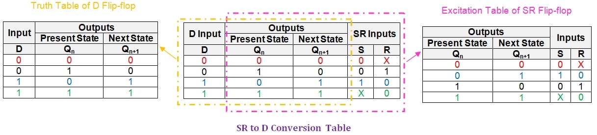
Figure 3: The breakdown of an SR-to-D conversion table. Click to enlarge.
Next, we need to obtain the logical expressions for the S and R input pins in terms of D and the present-state literal, Qn. We can do this using a simplification technique like that of K-maps. You can learn more about this technique here.
In this case, the technique yields a K-map as shown in Figure 4:
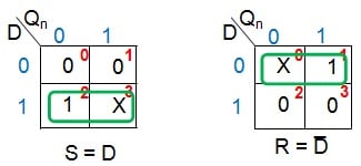
Figure 4: K-map simplification for the conversion of an SR-to-D flip-flop
From Figure 4, we can conclude that the given SR flip-flop can be made functionally equivalent to a D flip-flop by driving its S and R inputs by D and D̅, respectively. Thus, the required digital system can be designed by using a single NOT gate as shown by Figure 5:
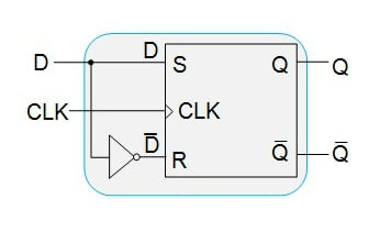
Figure 5: An SR flip-flop functioning as a D flip-flop
Having designed the system, our next step is to verify its functionality by using an SR-to-D verification table as shown in Figure 6:
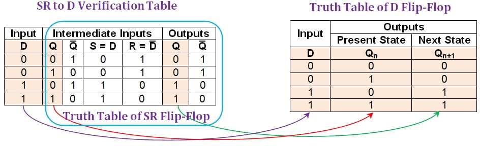
Figure 6: Comparison between an SR-to-D verification table and the truth table of D flip-flop. Click to enlarge.
From the verification table shown in Figure 6, it is evident that the entries in its first, second, and sixth columns (shaded in beige) are identical to the entries found in the truth table of the D flip-flop. This indicates that the system designed using the given SR flip-flop will behave exactly as a D flip-flop.
Conversion of an SR-to-T Flip-Flop
In order to convert the given SR flip-flop into T-type, we have to first write the SR-to-T conversion table, which is shown in Figure 7:
.jpg)
Figure 7: An SR-to-T conversion table. Click to enlarge.
Now, we need to express the inputs S and R in terms of T and the present-state literal, Qn. This can be accomplished by simplifying their logical expressions using the K-map technique (Figure 8).
.jpg)
Figure 8: K-map simplification for S and R inputs in terms of T and Qn
From Figure 8, it can be noted that the SR flip-flop can be made to function as a T flip-flop with two actions:
- Connect the S input to the output of a two-input AND gate which is driven by the user-provided input, T, and the negation of the flip-flop's present-state, Q̅n
- Connect the R input to the output of a two-input AND gate which is driven by the user-defined input, T, and the present-state of the flip-flop, Qn
Thus the resultant digital system would be as shown in Figure 9:
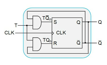
Figure 9: An SR flip-flop functioning as a T flip-flop
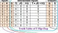
Now we shall check our conversion technique by writing the SR-to-T verification table, which is shown in Figure 10:
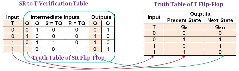
Figure 10: The comparison between an SR-to-T verification table and the truth table of a T flip-flop. Click to enlarge.
Here it is seen that the entries in the first, second, and the sixth columns of the SR-to-T verification table (shaded in beige) match exactly the entries in the truth table of the T flip-flop. From this, one can conclude that the system designed converts the given SR flip-flop into a T flip-flop. This indicates a successful conversion process.
An Overview
In this article, we explained the process of verifying the flip-flop conversion technique for the SR-to-JK flip-flop conversion that was explained in Part I.
Further, the same conversion and verification techniques were applied to two more examples wherein the given SR flip-flop was converted into a D flip-flop and a T flip-flop.
In Part III of this series, we will present the conversion of a JK flip-flop to other flip-flop types and also verify the conversions.
Next Article in Series: Conversion of Flip-Flops, Part III — JK Flip-Flops
Related Content


This brings back memories. I did this technique in the 70’s when we had Karnaugh Maps (your k map). We were always taught to use J-K devices for everything. The more useful exercises were to make counters that had obscure count pattern. A 10 stage counter would have 20 karnaugh maps, one each for J & K on each device.