Facebook
 Google
 GitHub
 Linkedin
555 Lab - Advanced Red LED Flasher
Project Overview
The circuit shown in the previous experiment, 555 Lab - Red LED Flasher, has one big drawback, a lack of light-emitting diode (LED) current control. This experiment begins with the same basic 555 circuit and then adds transistors to drive the LED and a resistor to limit the current (Figure 1).
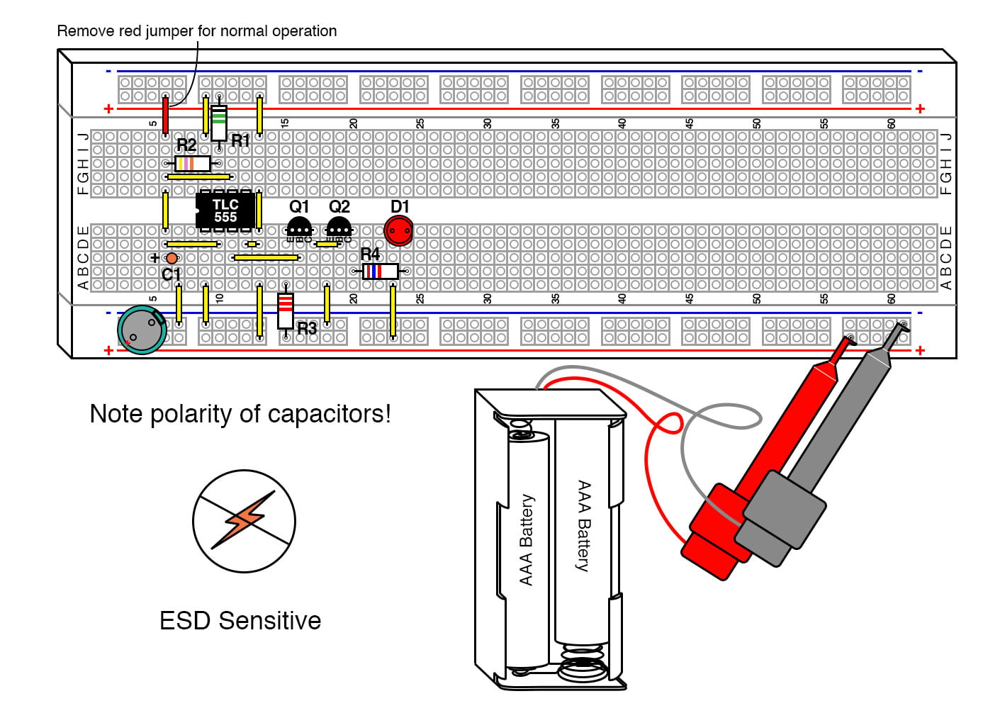
Figure 1. Breadboard implementation of the 555 timer LED flasher with transistor current drive.
Parts and Materials
- Two AAA batteries
- Battery clip
- A digital voltmeter (DVM) or volt-ohmmeter (VOM)
- U1 - CMOS TLC555 timer IC.
- Note: This is a static-sensitive part. If you do not use protection as described in the electrostatic discharge (ESD) chapter, you run the risk of destroying it.
- Q1 - 2N3906 PNP transistor or equivalent
- Q2 - 2N2222 NPN transistor or equivalent
- D1 - Red LED
- R1 - 1.5 MΩ 1/4W 5% resistor
- R2 - 47 kΩ 1/4W 5% resistor
- R3 - 2.2 kΩ 1/4W 5% resistor
- R4 - 27 Ω 1/4W 5% resistor
- C1 - 1 µF tantalum capacitor
- C2 - 100 µF electrolytic capacitor
Learning Objectives
- Learn a practical application for an RC time constant
- Learn one of several 555 timer astable multivibrator configurations
- Working knowledge of duty cycle
- How to handle ESD-sensitive parts
- How to use transistors to improve current gain
- How to calculate the correct resistor to limit LED current
Instructions
Step 1: Build the 555 oscillator circuit shown in Figures 1 and 2.
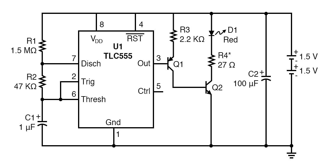
Figure 2. Schematic diagram of the 555 timer LED flasher with transistor current drive.
Omit the red jumper wire shown at the upper left of Figure 1. The LED should start flashing roughly every 1 second.
Step 2: Measure the forward voltage of the LED, VF, by adding the jumper shown in red in Figure 1. Adding this jumper will turn the LED on full-time. Use a voltmeter to measure the voltage drop across the LED while it is turned on.
Step 3: Calculate the approximate current through the LED using the following equation:
$$I_{LED} \approx \frac{( V_{DD} - V_F)}{R4}$$
LEDs can have a lot of variation in the forward voltage. Using that equation with our supply voltage of 3.0 V and an R4 of 27 Ω:
- If VF = 2.5 V, the LED current would be 18.5 mA
- If VF = 2.1 V, the LED current would be 33.3 mA
- If VF = 1.5 V, the LED current would be 55.6 mA
A forward current of 55.6 mA might cause the LED to burn out. Not to mention it would negatively impact the battery life of the system. If we want to target an LED forward current of 20 mA (a typical value), we can calculate values for R4 using this equation:
$$R4 = \frac{( V_{DD} - V_F)}{I_{LED}} = \frac{( 3.0 - V_F)}{0.02}$$
Using that equation, we can calculate the following resistance values for R4:
- If VF = 2.5 V, use a 25 Ω resistor
- If VF = 2.1 V, use a 45 Ω resistor
- If VF = 1.5 V, use a 75 Ω resistor
Step 4: It was mentioned in the previous experiment that capacitor, C2, extended the life of the batteries. Try removing this capacitor and see what happens. After a time, you will begin to notice a dimming of the LED. After a week or two, the circuit will die without the capacitor. Now, place the capacitor back into the circuit. The circuit will resume working in a couple of seconds. The capacitor provides the surge current required when the LED turns on. This flasher will work for 3 months using fresh alkaline AAA batteries.
Theory of Operation
The complimentary metal-oxide semiconductor (CMOS) 555 oscillator was explained fully in the previous 555 Lab - Red LED Flasher experiment, so the transistor driver will be the focus of this explanation. The transistors, Q1 and Q2, used to drive the LED are non critical. They are designed to minimize the load on the TLC555 IC, while still turning Q2 on fully. This is important because as the battery voltage approaches 2 V, the drive from the TLC555 is reduced to its minimum value and might otherwise not be able directly drive an LED. Bipolar transistors make excellent switches in thes types of applications.
The transistor driver combines elements of a common collector configuration on Q1, along with the common emitter configuration of Q2. This allows for very high input resistance while allowing Q2 to turn on fully.
The input resistance of a transistor is the β (gain) of the transistor times the emitter resistor. If Q1 has a gain of 50 (a minimum value) then the driver loads the TLC555 with more than 100 KΩ. This provides a high impedance load to the 555 output, so it does not need to drive much current. Transistors can have large variations in gain, even within the same family.
When Q1 turns on, 1 mA is passed to Q2. This is more than enough to turn Q2 fully on, which is referred to as saturation. Q2 is used as a simple switch for the LED.
Related Content
Learn more about the fundamentals behind this project in the resources below.
Textbook:
- Multivibrators
- Voltage and Current Calculations
- Solving for Unknown Time
- Electrostatic Discharge
- Bipolar Junction Transistors
Calculator:
Projects:
Worksheet: