 Facebook
 Google
 GitHub
 Linkedin
Exactly How Schmitt Trigger Oscillators Work
This article is intended to help readers understand the good and the bad traits of Schmitt Trigger RC oscillators, which are especially important because they are present in the internal oscillator in popular MCUs.
This article is intended to help readers understand the good and the bad traits of Schmitt Trigger RC oscillators, which are especially important because they are present in the internal oscillator in popular MCUs.
Oscillators are a must in digital systems, as sequential logic requires some clock signal that causes the state to change. In particular, Schmitt Trigger oscillators are present in low-cost microcontrollers as a way to provide a reliable clock signal, without requiring an external resonator or oscillator.
Let’s explore the basic principle of operation of these circuits.
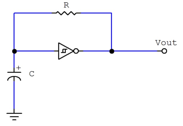
An RC Oscillator
First, let’s look at a very simple RC oscillator:
You may already know that the frequency of this oscillator can be calculated by
$$f= {k \over RC}$$
where k is a constant usually between 0.2 and 1.
This is a rough estimate that depends on several conditions that need to be met. Let’s analyze this circuit and derive an expression for the output frequency.
How RC Oscillators Work
Non-controlled oscillators are special blocks in that they don’t have an input. Instead, they consist of an amplifier and a feedback loop. In the case of this circuit, the feedback loop is an RC network, which behaves as the transient model of the series RC circuit.
Series RC Circuit Basics
In this circuit, usually two phases are considered: charge and discharge. The following circuit is capable of making the capacitor go through both phases:
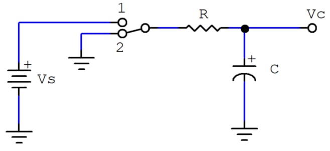
When the switch is in position 1, the capacitor is charging. Its voltage behaves as follows over time.
$$V_C(t)=V_S(1-e^{-{t \over RC}})$$
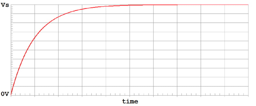
The voltage in the capacitor goes from 0V to Vs asymptotically in the charge phase.
Position 2 enables the discharge phase, in which the capacitor’s voltage does the following.
$$V_C(t)=V_S \; e^{-{t \over RC}}$$
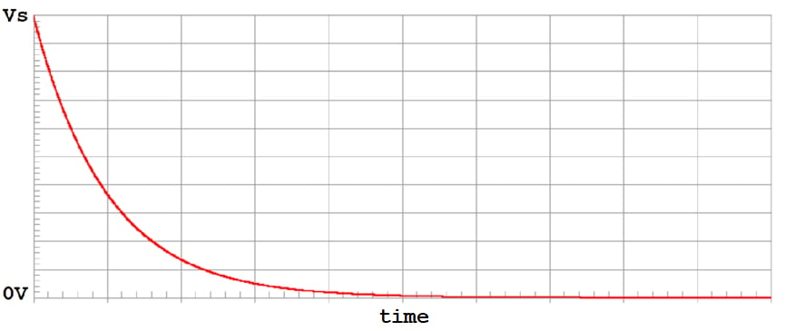
The voltage in the capacitor goes from Vs to 0V asymptotically in the discharge phase.
These two phases are almost enough for designing an RC oscillator. The only thing we need now is hysteresis; that is, responding to two voltage levels to keep the capacitor’s voltage “bouncing” between these two levels in a reliable manner.
Schmitt Trigger Gates
These are special gates that do not respond to a single voltage threshold in their inputs. Instead, their inputs respond to one rising (higher) threshold voltage and one falling (lower) threshold voltage: Whenever the input voltage exceeds the rising threshold, the input logical level is regarded as high, and whenever the input voltage drops below the falling threshold, the input is considered low. This means that a Schmitt Trigger input has some means of recalling its current level, which is the last level it changed to.
This behavior is known as hysteresis, and it’s ideal for oscillators, as you’ll see below.
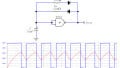
The following figure shows a noisy negative pulse that goes from 5V to 0V and then back up to 5V, and the output of a regular inverter and two different Schmitt Trigger inverters when fed that noisy signal:

A (Red): A Noisy signal fed to three inverters, which will output the inverted value of whatever the noisy signal is interpreted as in their inputs. B (Blue): The output of a 74LS04 regular TTL inverter. C (Green): The output of a 74LS14 Schmitt Trigger TTL inverter. D (Orange): The output of a Schmitt Trigger CMOS NAND gate configured as an inverter.
Notice how the noise is transferred to the regular inverter, as opposed to the Schmitt Trigger inverters (this noise can be seen in the leading rising edge and the trailing falling edge of the 74LS04 output). This happens because the 74LS04 responds to a single threshold that is somewhere around 1.2V.
Also notice the different times at which the Schmitt Trigger inverters react first and last. This difference corresponds to their different hysteresis voltages (the difference between their thresholds). The 4093 has a larger hysteresis, meaning that it has a better immunity to this kind of noise.
From this point on, let’s refer to the rising threshold voltage as $$V_{T+}$$ and to the falling threshold voltage as $$V_{T-}$$, as they are known is many datasheets.
Putting It All Together
The basic oscillator consists of a series RC circuit driven by a Schmitt Trigger inverter. The inverter’s input is the capacitor’s voltage. Thus, the inverter is forced to:
- Charge the capacitor when its voltage is below $$V_{T+}$$ and the output is high.
- Discharge the capacitor when its voltage is above $$V_{T-}$$ and the output is low.
Here’s an implementation of this oscillator with a 74LS14 Schmitt Trigger inverter:

An RC oscillator implemented with a 74LS14 inverter. In the plot, A (red) is the output voltage, and B (blue) is the voltage in the capacitor. The limits between which this voltage is bouncing are the threshold voltages of the inverter.
How to Calculate the Output Frequency
To produce an equation for the frequency of the output signal, we need to know its period, that is, how long it takes a cycle to complete. This is easily calculated by adding the high pulse width and the low pulse width.
The high pulse width is the duration of the high level in the output, which also happens to be the time it takes for the capacitor’s voltage to reach the rising threshold voltage $$V_{T+}$$. At the beginning of the very first cycle, the capacitor can be assumed to be discharged, so its voltage will be zero. This single charging phase (the first one), will only happen once and will not contribute to the steady-state frequency.
Thus, disregarding the first charging phase, the steady state high pulse width is the time it takes the capacitor’s voltage to rise from the falling threshold voltage to the rising threshold voltage, while attempting to reach the high level voltage. This can be derived from the following equation:
$$V_C(t)=(V_{High}-V_{T-}) \left ( 1-e^{-{t\over{RC}}} \right )+V_{T-}$$
This is the behavior of the capacitor's voltage in the charging phase starting at $$V_{T-}$$. So, to calculate the time it takes to reach $$V_{T+}$$, we just have to evaluate the function at $$V_{T-}$$ and solve for t. The value of t we’re interested in is the high pulse width, which we’ll call th.
$$V_{T+}=(V_{High}-V_{T-}) \left ( 1-e^{-{t_h\over{RC}}} \right )+V_{T-}\\\\$$
$${V_{T+} -V_{T-} \over V_{High}-V_{T-}}=1-e^{-{t_h\over{RC}}}\\\\$$
$$e^{-{t_h\over{RC}}}=1-{V_{T+} -V_{T-} \over V_{High}-V_{T-}}\\\\$$
$$-{t_h\over{RC}}=ln \left ( 1-{V_{T+} -V_{T-} \over V_{High}-V_{T-}} \right )\\\\$$
$$t_h=-RC \; ln \left ( 1-{V_{T+} -V_{T-} \over V_{High}-V_{T-}} \right )\\\\$$
$$t_h=-RC \; ln \left ( {V_{High}-V_{T+} \over V_{High}-V_{T-}} \right )\\\\$$
$$t_h=RC \; ln \left ( {V_{High}-V_{T-} \over V_{High}-V_{T+}} \right )\\\\$$
Now, for the low pulse width tl, it’s the time it takes for the capacitor’s voltage to drop from the rising threshold $$V_{T+}$$ down to the falling threshold $$V_{T-}$$, while attempting to reach zero volts, as follows.
$$V_C(t)=V_{T+} \; e^{-{t\over{RC}}}$$
Again, evaluating at the target $$V_{T-}$$, we can solve for tl:
$$V_{T-}=V_{T+} \; e^{-{t_l\over{RC}}}\\\\$$
$$e^{-{t_l\over{RC}}}={V_{T-} \over V_{T+}}\\\\$$
$$-{t_l\over{RC}}=ln \left ( {V_{T-} \over V_{T+}} \right ) \\\\$$
$$t_l=-RC \; ln \left ( {V_{T-} \over V_{T+}} \right )\\\\$$
$$t_l=RC \; ln \left ( {V_{T+} \over V_{T-}} \right )$$
Thus, the period of the output signal comes to
$$T=t_h+t_l\\\\$$
$$T=RC \; ln \left ( {V_{High}-V_{T-} \over V_{High}-V_{T+}} \right )+RC \; ln \left ( {V_{T+} \over V_{T-}} \right )\\\\$$
$$T=RC \left [ ln \left ( {V_{High}-V_{T-} \over V_{High}-V_{T+}} \right ) + ln \left ( {V_{T+} \over V_{T-}} \right ) \right ]\\\\$$
$$T=RC \; ln \left ( {V_{High}-V_{T-} \over V_{High}-V_{T+}} \times {V_{T+} \over V_{T-}} \right ) \\\\$$
And we know that the frequency is the reciprocal of the period, so our general equation for the frequency finally looks as follows.
$$f={ 1 \over T}\\\\$$
$$f={1 \over RC \; ln \left ( {V_{High}-V_{T-} \over V_{High}-V_{T+}} \times {V_{T+} \over V_{T-}} \right ) } \\\\$$
A commonly desirable condition, which happens to simplify the expression for the period, is generating a square wave. This means that the high pulse width must equal the low pulse width so that the signal has a duty cycle of 50%.
This can be achieved by using a Schmitt Trigger gate with threshold voltages equally separated to the logic levels. One popular Schmitt Trigger configuration is thus that of having threshold voltages at 1/3 and 2/3 of VDD, the supply voltage.
For example, in a TTL circuit (0V=low, and 5V=high), a convenient pair of threshold voltages would be 1.33V and 2.67V, because in both the charge and discharge phases the RC circuit would be exposed to an initial voltage of 1.33V.
So, if this symmetrical thresholds condition holds, the general equation for period comes to this much simpler form:
$$T=RC \; ln \left ( {V_{High}-V_{T-} \over V_{High}-V_{T+}} \times {V_{T+} \over V_{T-}} \right ) \\\\$$
$$T=RC \; ln \left ( {V_{T+} \over V_{T-}} \times {V_{T+} \over V_{T-}} \right ) \\\\$$
$$T=RC \; ln \left [ \left ( {V_{T+} \over V_{T-}} \right ) ^2 \right ]\\\\$$
$$T=2RC \; ln \left ( {V_{T+} \over V_{T-}} \right ) \\\\$$
$$f={1 \over 2RC \; ln \left ( {V_{T+} \over V_{T-}} \right ) }\\\\$$
Conclusion
RC oscillators are a simple solution to the ubiquitous problem of generating a digital, stable-enough clock signal. One obvious advantage of this circuit when compared to other oscillators is its simplicity, and the basic equations we just derived make it a very easy to implement solution.
In a follow-up article entitled How to Design Schmitt Trigger Oscillators, we’ll explore some complications and considerations you may want to keep in mind when using an RC oscillator to make sure it will achieve its best performance.


Wonderful and easy understanding explanation