
 Facebook
 Google
 GitHub
 Linkedin
Digital Circuits
TTL Logic Gates
25 questions By Tony R. Kuphaldt
-
Question 4 of 25
The simplest type of digital logic circuit is an inverter, also called an inverting buffer, or NOT gate. Here is a schematic diagram for an inverter gate constructed from bipolar transistors (transistor-to-transistor-logic, also known as TTL), shown connected to a SPDT switch and an LED:
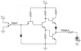
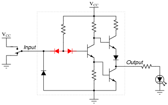
The left-most transistor in this schematic is actually not being used as a transistor, but rather it functions as a “steering diode” network, like this:
Determine the status of the LED in each of the input switch’s two positions. Denote the logic level of switch and LED in the form of a truth table:

Reveal answer
Notes:Have your students explain the operation of this TTL circuit, describing how the inverse logic state is generated at the output terminal, from a given input state.
-
Question 5 of 25
The following is an internal schematic of a TTL logic gate. Based on your analysis of the transistor circuit, determine what type of gate (AND, OR, NAND, NOR, XOR, etc.) it is:
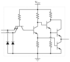
Hint: the double-emitter transistor is being used as a pair of diodes, and not as an amplifying device!

Reveal answerThis is a NAND gate circuit.
Notes:TTL circuits are actually quite easy to analyze compared to analog amplifier circuits! Discuss with your students the use of a dual-emitter transistor as a “steering” diode network: this is a trick used by IC manufacturers, to obtain three diodes for the “price” of one transistor.
-
Question 6 of 25
A very important concept to understand in digital circuitry is the difference between current sourcing and current sinking. For instance, examine this TTL inverter gate circuit, connected to a load:
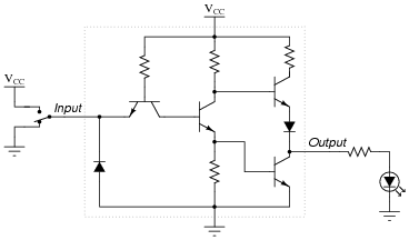
The output circuitry of this particular gate is commonly referred to as “totem-pole,” because the two output transistors are stacked one above the other like figures on a totem pole. Is a gate circuit with a totem-pole output stage able to source load current, sink load current, or do both?
Reveal answerTTL gates equipped with totem-pole output circuitry are able to both source and sink load current. In this particular case, the way the load (LED) is connected to the output of the gate, the gate will only source current. However, the gate is capable of sinking current from a load, if only the load were connected differently.
Follow-up question: does the input device driving this TTL gate circuit (the switch in this particular example) have to source current, sink current, or both?
Challenge question: explain how you would calculate the current sourcing and current sinking abilities of this logic gate circuit, if you were given the internal component values and parameters.
Notes:The very important concept of sourcing versus sinking is best understood from the perspective of conventional current flow notation. The terms seem backward when electron flow notation is used to track current through the output transistor.
One point of confusion I’ve experienced among students is that current may go either direction (in or out) of a gate with totem-pole output transistors (able to sink or source current). Some students seem to have a conceptual difficulty with current going in to the output terminal of a gate circuit, because they mistakenly associate the “out” in output as being a reference to direction of current, rather than direction of information or data.
An analogy I’ve used to help students overcome this problem is that of two people carrying a long pole:

Suppose these people are in a dark, noisy room, and they use the pole as a means of simple communication between them. For example, one person could tug on the pole to get the other person’s attention. Perhaps they could even develop a simple code system for communicating thoughts (1 tug = hello ; 2 tugs = good-bye ; 3 tugs = I think this is a silly way to communicate ; 4 tugs = let’s leave this room ; etc.). If one of the persons pushes on the pole rather than pulls on the pole to get the other person’s attention, does the direction of the pole’s motion change the direction of the communication between the two persons? Of course not. Well, then, does the direction of current through the output terminal of a gate change the direction that information flows between two interconnected gates? Whether a gate sources current or sinks current to a load has no bearing on the “output” designation of that gate terminal. Either way, the gate is still “telling the load what to do” by exercising control over the load current.


