Facebook
 Google
 GitHub
 Linkedin
Analog Integrated Circuits
Voltage/Current Converter OpAmp Circuits
9 questions By Tony R. Kuphaldt
-
Question 7 of 9
Predict how the operation of this current regulator circuit will be affected as a result of the following faults. Consider each fault independently (i.e. one at a time, no multiple faults):
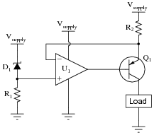
- Resistor R1 fails open:
- Resistor R2 fails open:
- Solder bridge (short) across resistor R2:
- Zener diode D1 fails shorted:
- Zener diode D1 fails open:
- Load fails shorted:
- Wire between opamp output and transistor base breaks open:
For each of these conditions, explain why the resulting effects will occur.
Reveal answer- Resistor R1 fails open: Load current falls to zero.
- Resistor R2 fails open: Load current falls to zero.
- Solder bridge (short) across resistor R2: Load current increases.
- Zener diode D1 fails shorted: Load current falls to zero.
- Zener diode D1 fails open: Load current increases.
- Load fails shorted: Load current remains the same.
- Wire between opamp output and transistor base breaks open: Load current falls to zero.
Follow-up question: which of the two opamp power terminals (Vsupply or Ground) carries more current during normal operation, and why?
Notes:The purpose of this question is to approach the domain of circuit troubleshooting from a perspective of knowing what the fault is, rather than only knowing what the symptoms are. Although this is not necessarily a realistic perspective, it helps students build the foundational knowledge necessary to diagnose a faulted circuit from empirical data. Questions such as this should be followed (eventually) by other questions asking students to identify likely faults based on measurements.
-
Question 8 of 9
The simplest electronic device capable of converting a current signal into a voltage signal is a resistor:
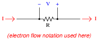
Precision resistors typically work very well for this purpose, especially when the amount of voltage dropped across it is of little consequence. This is why shunt resistors are frequently used in power circuitry to measure current, a low-resistance “shunt” resistance element dropping voltage in precise proportion to the current going through it.
However, if we cannot afford to drop any voltage across a resistance in the circuit, this technique of current-to-voltage conversion will not be very practical. Consider the following scientific apparatus, used to measure the photoelectric effect (electrons emitted from a solid surface due to light striking it):
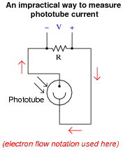
The current output by such a phototube is very small, and the voltage output by it is smaller yet. If we are to measure current through this device, we will have to find some way other than a shunt resistor to do it.
Enter the operational amplifier, to the rescue! Explain how the following opamp circuit is able to convert the phototube’s weak current signal into a strong voltage signal, without imposing any significant resistance into the phototube circuit:
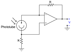
Reveal answerThe design of this circuit is complicated by the existence of bias currents at the opamp inputs. You may find it helpful to analyze a simplified version of the same circuit. Please bear in mind that this simplified circuit would only work if the opamp had absolutely no input bias currents at all:

Notes:Note to your students that this is one of those applications where even “tiny” input bias currents can affect the results. In this particular case, the phototube outputs miniscule current at best, and so we must compensate for the existence of opamp bias currents.
-
Question 9 of 9
Shown here is a simple circuit for constructing an extremely high input impedance voltmeter on a wireless breadboard, using one half of a TL082 dual op-amp:
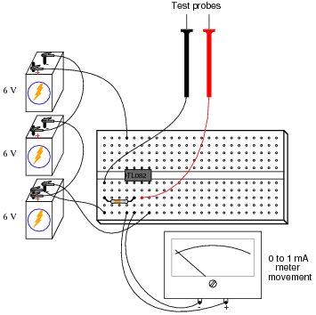
Draw a schematic diagram of this circuit, a calculate the resistor value necessary to give the meter a voltage measurement range of 0 to 5 volts.
Reveal answer
R = 5 kΩ
Follow-up question: determine the approximate input impedance of this voltmeter, and also the maximum voltage it is able to measure with any size resistor in the circuit.
Notes:This is a very practical circuit for your students to build, and they may find it outperforms their own (purchased) voltmeters in the parameter of input impedance! Be sure to ask them where they found the information on input impedance for the TL082 op-amp, and how they were able to determine the maximum input voltage for a circuit like this.