
 Facebook
 Google
 GitHub
 Linkedin
DC Electric Circuits
Voltage Divider Circuits
37 questions By Tony R. Kuphaldt
-
Question 34 of 37
Explain what will happen to the first load’s voltage and current in this voltage divider circuit if the second load develops a short-circuit fault:

Reveal answerIdeally, the first load’s voltage and current will remain unaffected by any fault within load #2. However, in the event of a short-circuit in load #2, the source voltage will almost surely decrease due to its own internal resistance. In fact, it would not be surprising if the circuit voltage decreased almost to zero volts, if it is a “hard” short in load #2!
Notes:While it is important for students to realize that the second load constitutes a separate parallel branch in the circuit and therefore (ideally) has no effect on the rest of the circuit, it is crucial for them to understand that such an ideal condition is rare in the real world. When “hard” short-circuits are involved, even small internal source resistances become extremely significant.
-
Question 35 of 37
Size all three resistors in this voltage divider circuit to provide the necessary voltages to the loads, given the load voltage and current specifications shown:

Assume a bleed current of 1.5 mA. As part of your design, include the power dissipation ratings of all resistors.
Reveal answerR1 = 545.5 Ω, rated for at least 148.5 mW dissipation (\(\frac{1}{4}\) watt recommended).
R2 = 933.3 Ω, \(\frac{1}{8}\) watt power dissipation is more than adequate.
R3 = 3.2 k Ω, \(\frac{1}{8}\) watt power dissipation is more than adequate.
Notes:Nothing special to comment on here, just a straightforward voltage divider design problem.
-
Question 36 of 37
Old vacuum-tube based electronic circuits often required several different voltage levels for proper operation. An easy way to obtain these different power supply voltages was to take a single, high-voltage power supply circuit and “divide” the total voltage into smaller divisions.
These voltage divider circuits also made provision for a small amount of “wasted” current through the divider called a bleeder current, designed to discharge the high voltage output of the power supply quickly when it was turned off.
Design a high-voltage divider to provide the following loads with their necessary voltages, plus a “bleeder” current of 5 mA (the amount of current going through resistor R4):
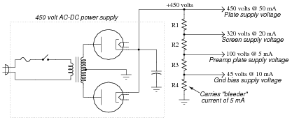
Reveal answer- R1 = 3.25 kΩ
- R2 = 11 kΩ
- R3 = 3.67 kΩ
- R4 = 9 kΩ
Follow-up question: how would the various output voltages (plate, screen, preamp, etc.) be affected if the bleeder resistor were to fail open? You don’t need to calculate anything, but just give a qualitative answer.
Notes:Be sure to ask your students how they obtained the solution to this problem. If no one was able to arrive at a solution, then present the following technique: simplify the problem (fewer resistors, perhaps) until the solution is obvious, then apply the same strategy you used to solve the obvious problem to the more complex versions of the problem, until you have solved the original problem in all its complexity.





Plus signs are missing from these questions and answers, such as in question 11, where the denominator of the voltage divider equation appears as “R1 R2 R3” instead of “R1+R2+R3”. Same in the answer to question 15. Likely elsewhere as well, as Find shows no results for “+” anywhere on the page. I’m using Chrome 88.0.4324.182 on Windows 10, but same on Firefox & Edge. HTML source for the page shows it as “R1 R2 R3”, so it isn’t just a display problem.
Iam a student and i need an explain for this answers how can I get an explanation ?
Ca any one tell in detail how
The formula got formed like this !! ( ER= Et(R/Rt)) thank you