
 Facebook
 Google
 GitHub
 Linkedin
DC Electric Circuits
Voltmeter Design
18 questions By Tony R. Kuphaldt
-
Question 7 of 18
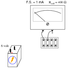
We know that connecting a sensitive meter movement directly across the terminals of a substantial voltage source (such as a battery) is a Bad Thing. So, I want you to determine what other component(s) must be connected to the meter movement to limit the current through its coil, so that connecting the circuit to a 6-volt battery results in the meter’s needle moving exactly to the full-scale position:
Reveal answer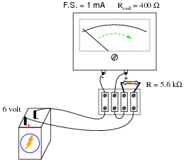
Notes:Beginning students sometimes feel “lost” when trying to answer a question like this. They may know how to apply Ohm’s Law to a circuit, but they do not know how to design a circuit that makes use of Ohm’s Law for a specific purpose. If this is the case, you may direct their understanding through a series of questions such as this:
- Why does the meter movement “peg” if directly connected to the battery?
- What type of electrical component is good at limiting current?
- How might we connect this component to the meter (series or parallel)? (Draw both configurations and let the student determine for themselves which connection pattern fulfills the goal of limiting current to the meter.)
The math is simple enough in this question to allow solution without the use of a calculator. Whenever possible, I challenge students during discussion time to perform any necessary arithmetic “mentally” (i.e. without using a calculator), even if only to estimate the answer. I find many American high school graduates unable to do even very simple arithmetic without a calculator, and this lack of skill causes them no small amount of trouble. Not only are these students helpless without a calculator, but they lack the ability to mentally check their calculator-derived answers, so when they do use a calculator they have no idea whether their answer is even close to being correct.
-
Question 8 of 18
Calculate the necessary resistance value and power rating for Rrange in order to make the meter movement respond as a voltmeter with a range of 0 to 100 volts:
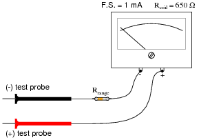
Reveal answerRrange = 99.35 k Ω, \(\frac{1}{8}\) watt will be sufficient.
Notes:This is really nothing more than a simple series circuit problem, although the context of it being a voltmeter seems to confuse some students. If you find a large percentage of your class not understanding where to begin in a problem such as this, it means they really don’t understand series circuits - all they learned to do when studying series resistor circuits before is to follow an easy sequence of steps to find voltages and currents in series resistor circuits. They did not learn the concepts well enough to abstract to something that looks just a little bit different.
-
Question 9 of 18
Calculate the necessary resistance value and power rating for Rrange in order to make the meter movement respond as a voltmeter with a range of 0 to 50 volts:
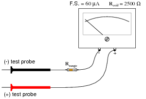
Reveal answerRrange = 830.83 k Ω, \(\frac{1}{8}\) watt will be sufficient.
Notes:This is really nothing more than a simple series circuit problem, although the context of it being a voltmeter seems to confuse some students. If you find a large percentage of your class not understanding where to begin in a problem such as this, it means they really don’t understand series circuits - all they learned to do when studying series resistor circuits before is to follow an easy sequence of steps to find voltages and currents in series resistor circuits. They did not learn the concepts well enough to abstract to something that looks just a little bit different.




The equations in the answer to question 3 are incorrect. The first two equations are missing Vt on the right side. Also, all of the equations are missing plus signs in the denominators.