
 Facebook
 Google
 GitHub
 Linkedin
DC Electric Circuits
Voltmeter Design
18 questions By Tony R. Kuphaldt
-
Question 16 of 18
What if this voltmeter suddenly stopped working when set in its middle range. The upper and lower ranges still function just fine, though. Identify the most likely source of the problem.
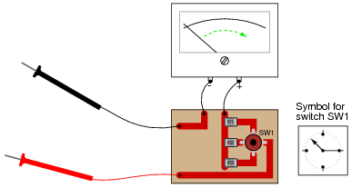
Reveal answerThe middle contact in switch SW2 is open. This, despite being the most likely failure, is not the only possible failure that could cause this problem (middle range not functioning)!
Challenge question: explain how you could verify the nature of the fault without using another meter.
Notes:Brainstorm some other alternative possibilities for causing the problem, along with diagnostic procedures to verify each one of them (using another meter, if necessary). Then, discuss with your students the reason why a switch failure is more likely than any of the other faults.
-
Question 17 of 18
Suppose you tried to measure the voltage at test point 2 (TP2) with a digital voltmeter having an input resistance of 10 MΩ. How much voltage would it indicate? How much voltage should it ideally indicate?
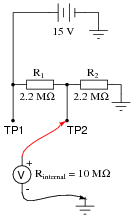
Reveal answerIdeally, of course, this voltage divider circuit should exhibit 7.5 volts at test point 2. The voltmeter, however, will register only 6.76 volts.
Follow-up question: is the voltmeter registering inaccurately, or is its connection to the circuit actually changing VTP2? In other words, what is the actual voltage at TP2 with the voltmeter connected as shown?
Notes:An analogy I often use to explain meter loading is the use of a pressure gauge to measure the air pressure in a pneumatic tire. In order to measure the pressure, some of the air must be let out of the tire, which of course changes the tire’s air pressure.
And in case you are wondering: no, this is not an example of Heisenberg’s Uncertainty Principle, popularly misunderstood as error introduced by measurement. The Uncertainty Principle is far more profound than this!
-
Question 18 of 18
Suppose you tried to measure the voltage at all three test points with an analog voltmeter having a sensitivity rating of 20 kΩ per volt, set on the 10 volt scale. How much voltage would it indicate at each test point? How much voltage should it ideally indicate at each test point?

Test point Ideal voltage Meter indication
TP1
TP2
TP3
Reveal answer
Test point Ideal voltage Meter indication
TP1 5 V 5 V
TP2 4.138 V 0.805 V
TP3 1.293 V 0.197 V
Notes:An analogy I often use to explain meter loading is the use of a pressure gauge to measure the air pressure in a pneumatic tire. In order to measure the pressure, some of the air must be let out of the tire, which of course changes the tire’s air pressure.
And in case you are wondering: no, this is not an example of Heisenberg’s Uncertainty Principle, popularly misunderstood as error introduced by measurement. The Uncertainty Principle is far more profound than this!






The equations in the answer to question 3 are incorrect. The first two equations are missing Vt on the right side. Also, all of the equations are missing plus signs in the denominators.