 Facebook
 Google
 GitHub
 Linkedin
Nonlinear Conduction
“Advances are made by answering questions. Discoveries are made by questioning answers.”
—Bernhard Haisch, Astrophysicist
Ohm’s Law is a simple and powerful mathematical tool for helping us analyze electric circuits, but it has limitations, and we must understand these limitations in order to properly apply it to real circuits. For most conductors, resistance is a rather stable property, largely unaffected by voltage or current.
For this reason, we can regard the resistance of many circuit components as a constant, with voltage and current being directly related to each other.
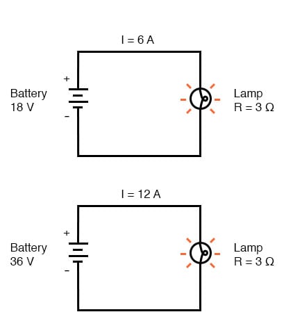
For instance, from our previous circuit example with the 3 Ω lamp, we calculated the current through the circuit by dividing the voltage by the resistance (I=E/R). With an 18 volt battery, our circuit’s current was 6 amps. Doubling the battery’s voltage to 36 volts resulted in a doubled current of 12 amps.
All of this makes sense, of course, as long as the lamp continues to provide exactly the same amount of friction (resistance) to the flow of current through it: 3 Ω.
The Voltage-Current Relationship Over Changing Resistance
However, reality is not always this simple. One of the phenomena explored in a later chapter is that of conductor resistance changing with temperature. In an incandescent lamp (the kind employing the principle of electric current heating a thin filament of wire to the point that it glows white-hot), the resistance of the filament wire will increase dramatically as it warms from room temperature to operating temperature.
If we were to increase the supply voltage in a real lamp circuit, the resulting increase in current would cause the filament to increase temperature, which would, in turn, increase its resistance, thus preventing further increases in the current without further increases in battery voltage.
Consequently, voltage and current do not follow the simple equation “I=E/R” (with R assumed to be equal to 3 Ω) because an incandescent lamp filament resistance does not remain stable for different currents.
The phenomenon of resistance changing with variations in temperature is one shared by almost all metals, of which most wires are made. For most applications, these changes in resistance are small enough to be ignored. In the application of metal lamp filaments, the change happens to be quite large.
This is just one example of “nonlinearity” in electric circuits. It is by no means the only example. A “linear” function in mathematics is one that tracks a straight line when plotted on a graph. The simplified version of the lamp circuit with a constant filament resistance of 3 Ω generates a plot like this:
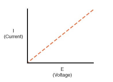
The straight-line plot of current over voltage indicates that resistance is a stable, unchanging value for a wide range of circuit voltages and currents. In an “ideal” situation, this is the case. Resistors, which are manufactured to provide a definite, stable value of resistance, behave very much like the plot of values seen above. A mathematician would call their behavior “linear.”
A more realistic analysis of a lamp circuit, however, over several different values of battery voltage would generate a plot of this shape:
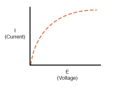
The plot is no longer a straight line. It rises sharply on the left, as voltage increases from zero to a low level. As it progresses to the right we see the line flattening out, the circuit requiring greater and greater increases in voltage to achieve equal increases in current.
If we try to apply Ohm’s Law to find the resistance of this lamp circuit with the voltage and current values plotted above, we arrive at several different values. We could say that the resistance here is nonlinear, increasing with increasing current and voltage. The nonlinearity is caused by the effects of high temperature on the metal wire of the lamp filament.
Another example of nonlinear current conduction is through gases such as air. At standard temperatures and pressures, air is an effective insulator. However, if the voltage between two conductors separated by an air gap is increased greatly enough, the air molecules between the gap will become “ionized,” having their electrons stripped off by the force of the high voltage between the wires.
Once ionized, air (and other gases) become good conductors of electricity, allowing electron flow where none could exist prior to ionization. If we were to plot current overvoltage on a graph as we did with the lamp circuit, the effect of ionization would be clearly seen as nonlinear:
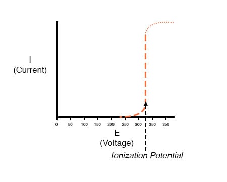
The graph shown is approximate for a small air gap (less than one inch). A larger air gap would yield a higher ionization potential, but the shape of the I/E curve would be very similar: practically no current until the ionization potential was reached, then substantial conduction after that.
Incidentally, this is the reason lightning bolts exist as momentary surges rather than continuous flows of electrons. The voltage built up between the earth and clouds (or between different sets of clouds) must increase to the point where it overcomes the ionization potential of the air gap before the air ionizes enough to support a substantial flow of electrons.
Once it does, the current will continue to conduct through the ionized air until the static charge between the two points depletes. Once the charge depletes enough so that the voltage falls below another threshold point, the air de-ionizes and returns to its normal state of extremely high resistance.
Many solid insulating materials exhibit similar resistance properties: extremely high resistance to current flow below some critical threshold voltage, then a much lower resistance at voltages beyond that threshold.
Once a solid insulating material has been compromised by high-voltage breakdown, as it is called, it often does not return to its former insulating state, unlike most gases. It may insulate once again at low voltages, but its breakdown threshold voltage will have been decreased to some lower level, which may allow breakdown to occur more easily in the future.
This is a common mode of failure in high-voltage wiring: insulation damage due to breakdown. Such failures may be detected through the use of special resistance meters employing high voltage (1000 volts or more).
Components with Nonlinear Resistance
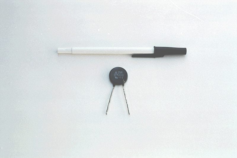
There are circuit components specifically engineered to provide nonlinear resistance curves, one of them being the varistor. Commonly manufactured from compounds such as zinc oxide or silicon carbide, these devices maintain high resistance across their terminals until a certain “firing” or “breakdown” voltage (equivalent to the “ionization potential” of an air gap) is reached, at which point their resistance decreases dramatically.
Unlike the breakdown of an insulator, varistor breakdown is repeatable: that is, it is designed to withstand repeated breakdowns without failure. A picture of a varistor is shown here:
There are also special gas-filled tubes designed to do much the same thing, exploiting the very same principle at work in the ionization of air by a lightning bolt.
Other electrical components exhibit even stranger current/voltage curves than this. Some devices actually experience a decrease in current as the applied voltage increases. Because the slope of the current/voltage for this phenomenon is negative (angling down instead of up as it progresses from left to right), it is known as negative resistance.

Most notably, high-vacuum electron tubes known as tetrodes and semiconductor diodes known as Esaki or tunnel diodes exhibit negative resistance for certain ranges of applied voltage.
Ohm’s Law is not very useful for analyzing the behavior of components like these where resistance varies with voltage and current. Some have even suggested that “Ohm’s Law” should be demoted from the status of a “Law” because it is not universal. It might be more accurate to call the equation (R=E/I) a definition of resistance, befitting of a certain class of materials under a narrow range of conditions.
For the benefit of the student, however, we will assume that resistances specified in example circuits are stable over a wide range of conditions unless otherwise specified. I just wanted to expose you to a little bit of the complexity of the real world, lest I give you the false impression that the whole of electrical phenomena could be summarized in a few simple equations.
REVIEW:
- The resistance of most conductive materials is stable over a wide range of conditions, but this is not true of all materials.
- Any function that can be plotted on a graph as a straight line is called a linear function. For circuits with stable resistances, the plot of current over voltage is linear (I=E/R).
- In circuits where resistance varies with changes in either voltage or current, the plot of current over voltage will be nonlinear (not a straight line).
- A varistor is a component that changes resistance with the amount of voltage impressed across it. With little voltage across it, its resistance is high. Then, at a certain “breakdown” or “firing” voltage, its resistance decreases dramatically.
- Negative resistance is where the current through a component actually decreases as the applied voltage across it is increased. Some electron tubes and semiconductor diodes (most notably, the tetrode tube and the Esaki, or tunnel diode, respectively) exhibit negative resistance over a certain range of voltages.
RELATED WORKSHEETS:


Does a negative resistance worksheet exist?