Facebook
 Google
 GitHub
 Linkedin
Choosing the Right TSN Tools to Meet a Bounded Latency
As automotive moves from domain to zonal networks, many different kinds of data end up sharing the same wires. This article looks at IEEE 802.1’s Time-Sensitive Networking (TSN) standards as a solution.
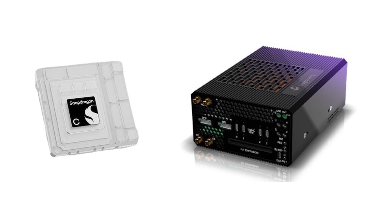
TSN may be new to many people even though the IEEE 802.1 Work Group has completed more than a dozen TSN standards over the last decade and some are already supported in HW, e.g. by NXP’s new SJA1110 Ethernet Switch. Many of these TSN standards are targeted at bounding the latency of a steam. With so many standards or “tools” available, the challenge of knowing what the proper “tool” to use and when is increasingly harder. This is especially true when considering that the TSN tools are intended to work together on the same port at the same time!
The Shaper Standards
Strict Priority Shaper
The first IEEE 802.1 shaper was standardized in IEEE 802.1p-1998 and it defines the Strict Priority Selection algorithm used to select the next frame to be transmitted out a port for ports with multiple queues. These priority queues are referred to as Traffic Class (TC) queues in the standard. Today, there are many supported mechanisms in 802.1 that can be used to determine which TC a frame gets enqueued to. While most of these mechanisms are beyond the scope of this article, the original mechanism of using the per-port mapping of the frame’s 3-bit Priority Code Point (PCP) field contained in 802.1 Tagged frames is an integral part of TSN – as this is the mechanism used to indicate that some frames need to be treated differently.
Strict Priority was created to solve the problem of effective network management. Simply put, a network can’t be managed using the same wires that “data” traffic uses if the “data” traffic is using all of the wire’s bandwidth and there is no preference (i.e., a higher priority) given to the network management traffic.
Figure 1 shows the solution via an egress queue structure typically used in the transmit path of bridges and end station’s NICs (Network Interface Controller).

Figure 1. Basic Egress Queue Model with Strict Priority.
The 1998 standard supports 1 to 8 TC queues and the figure shows the default mapping of a frame’s 3-bit PCP value to TC queue for an 8-queue design ( PCP 0 being a higher priority than PCP 1 is as it is in the standard). The highest TC (8) is labeled Network Management as this is the queue where these frames need to go in order to solve the network management problems.
Credit-Based Shaper
More than 10 years passed before a new shaper was standardized in IEEE 802.1. That new shaper, the Credit-Based Shaper (CBS), was targeted to solve issues associated with audio and video streams, but it can also be used for other data types as well. Why? Because CBS was designed to solve the generic problem of bursting, which occurs regardless of the data type. Bursting (the transmission of multiple back-to-back frames) occurs naturally in bridges on bridge ports that are congestion points and in end-stations as a result of the way end-station (NIC) hardware and software are designed.
NICs are optimized to get the highest data throughput possible and use bursting to attain this goal.
If the network congestion point is in a bridge, that bridge could drop packets. Examples of congestion points are a Gigabit port switching data to a 100 Mb/s port, or two 100 Mb/s ports switching data to a single 100 Mb/s port. In both cases, the output data rate is less than the potential input data rate.
CBS addresses the packet dropping problem at the network congestion points and NICs by de-bursting the flows in hardware. It is configurable on a per TC basis, so flows mapped to a queue where CBS is enabled automatically have their transmit bursts removed without any changes to the “optimized” NIC drivers or bridge enqueueing mechanisms.
Figure 2 shows where CBS resides (along with other shapers discussed later).

Figure 2. Example of Simultaneous TSN Shaper Egress Queue Model.
In this example, it is important to note that the Network Management flows are moved to TC 6 and the CBS flows are in TC queues above Network Management. This works because the Audio Video Bridging (AVB) profile specification (IEEE 802.1BA) limits the total transmission rate of the CBS flows to be no more than 75% of the port’s output data rate. Network Management is the top priority of the remaining (non-reserved) bandwidth ensures that it can perform its original function.
Time-Aware Shaper
After the AVB set of standards was completed for the plug-and-play audio/video use case, it was clear that there were use cases that required lower latency from what AVB could provide. And these users were willing to engineer the network if needed in order to get lower latencies.
The Time Aware Shaper (TAS) started out as an exercise by the author to find the theoretically lowest possible latency and TAS is what was proposed and standardized (IEEE 802.1Qbv). TAS works best in applications that are cyclical, i.e., there are fixed periodic intervals when critical sensor data is transmitted and processed, and the resulting critical actuator commands are issued. Most industrial machines work on this concept as do many other systems.
TAS minimizes the latency for time-critical flows by ensuring that the port a frame is egressing (bridge or end-station) is idle at the time the critical flow is scheduled to egress the port. This minimizes the latency since the critical flow can start transmitting precisely at its scheduled time, as the port is not busy transmitting anything else. The timing of the packet transmission is accomplished by the addition of transmission gates to the output of each TC queue (the orange boxes in Figure 2). A timing schedule of gate opening and closings for each TC is also needed. If a gate is closed on a queue that TC cannot transmit any data.
The TAS schedule becomes easier to solve by minimizing the number of critical flows and TC queues that use this extremely lowest latency mechanism and by minimizing the number of gate opens and closes per cycle. This is shown in Figure 2 as only one TC is shown as “Scheduled” and this is TC 2 indicated by a PCP value of 0. How can a very low priority queue get lower latency than the TC queues above it? If it is the only TC with a gate open, it is by definition the highest priority during that transmission window.
Preemption
Preemption was developed as a standard at the same time as TAS. It was seen as an alternative for networks that were not Time Aware and it too gets very low latency, but not as low. Preemption is easier to use as there are no “Schedules” to work out. But it cost a lot in hardware, only works if its link partner also supports preemption, works best at 100 Mb/s or slower links, and the standard supports only one level of preemption, all of which minimizes its potential use cases.
Preemption interrupts a “preemptable” frame in the middle of its transmission. It then allows the “express” frame or frames to egress the port. Only then does it resume the transmission of the “preempted” frame where it left off. This interruption can occur multiple times on the same frame.
Preemption is a combination of two standards. The MAC mechanism and the codes sent down the wire is standardized in IEEE 802.3br. It defines two MACs, a pMAC (Preemptable MAC) and an eMAC (Express MAC). These can be seen on the right-hand side of Figure 2. Preemption has the following restrictions:
- Minimum fragment size is 64 bytes but can be negotiated by the link partner to be 128 or 256
- Fragment padding is not done so a fragment could be nearly twice the min fragment size
The partner standard for preemption (IEEE 802.1Qbu) defines which TC queue or queues are connected to the two MAC types. In Figure 2, TC 1 is the only TC connected to the eMAC. That means that any frame enqueued to TC 1 will preempt all the other TC queues (i.e., any data that is currently transmitting). Even though TC 1 is the lowest priority queue, it is effectively above all the other queues since it can preempt them! But only if its TAS gate is open.
Metrics for the Shaper Standards
The IEEE 802.1 Working Group designs their standards so they can work together at the same time, as each TC queue on a port can be configured with a different shaper. To make it easier to determine which shaper is the best one for a given job, metrics need to be evaluated. The ones addressed here are cost and performance. Availability is also an important metric as the perfect tool can’t help you if you can’t get it at any price. In general, the newer IEEE standards are less available and are not discussed.
Shaper Costs
The costs examined are:
- Engineering Complexity: The expected user difficulty or effort needed to get proper results.
- Wire Efficiency: The amount of data can go down the wire, including both the critical data and the background data.
Shaper Performance
It is quite difficult to get to the absolute worst-case numbers for a shaper as network topology or other parameters may come into play. Instead, using first-order approximations resulting in slightly larger latency numbers are used. Once the network is fully configured with all the expected streams, a network analysis tool needs to be used to calculate the accurate worst-case latency numbers.
Per hop latency equations for each shaper are shown below as these are easier to evaluate as a flow may traverse many hops. Only the network designer knows how many hops and what the maximum bounded latency target is for each flow.
Credit-Based Shaper (Multiple Classes are Supported)
- Class A ≈ tInterval + tMaxFrameSize
- tInterval: The observation interval of the Class (125 uSec as specified in AVB – but this can be changed for engineered networks!)
- tMaxFrameSize: The maximum size of an interfering frame + gaps, etc.
- Class B ≈ tInterval + tMaxFrameSize + tTimeForAllHigherFrames
- tTimeForAllHigherFrames: The time to transmit all Class A frames (+ gaps, etc.) for the duration of Class B’s tInterval (which is typically a multiple of Class A’s tInterval)
- Class C ≈ tInterval + tMaxFrameSize + tTimeForAllHigherFrames
- tTimeForAllHigherFrames: The time to transmit all Class A and Class B frames…
- Etc.
Time-Aware Shaper
- Store and Forward with Traffic Class Gate Open ≈ tDevice + tFrameSize
- tDevice: The delay through a Store and Forward bridge
- tFrameSize: The size of the frame passing through the bridge
tDevice is product specific. To advance the latency discussions in IEEE 802.1, a “rule-of-thumb” default was proposed, which works out to be ≈ 10.5 uSec for 100 Mb/s and 1.5 uSec for Gb/s.
Preemption
- Store and Forward Preemption ≈ tDevice + tFrameSize + tFramelet
- tDevice: The delay through a Store and Forward bridge
- tFrameSize: The size of the frame passing through the bridge
- tFramelet: 127 bytes + overhead if 64 byte fragmentation is enabled
tFramlet, is the largest part of a frame that can’t be preempted. If 64-byte fragmentation is being used then 127 bytes cannot be further fragmented as it would result in a fragment smaller than the minimum 64-byte requirement.
Link speed affects some of these parameters, but not the observation interval (tInterval). Therefore, results will be calculated for both Fast Ethernet (FE) and Gigabit Ethernet (GE). For easy comparison between shapers, the following parameters are used for all the shaper equations: tMaxFrameSize is 1542 (1522+20) bytes, tFrameSize is 64 bytes, tInterval is 125 uSec and all numbers are rounded up to the next highest uSec or 10th of a uSec.
Table 1 summarizes the cost and the calculated performance data for each of the TSN Shapers discussed with a proposed ranking.
Table 1. Latency TSN Tool Comparison in Lowest Latency Order

Both TAS and Preemption are much faster compared to CBS, but CBS is ranked first for the following reasons:
- It’s fast enough for a large number of applications
- It’s the only shaper on the list that is easy to use
- It’s the only shaper on the list that allows 100% of the wire’s bandwidth to be used
- And more than one TC can be used with different observation intervals/latencies. The other shapers are best limited to a single TC or their ease of use becomes hard.
CBS being easy to support more than one TC makes it quite is interesting. For example, standard AVB Class A audio traffic can be used in one TC, while at the same time as other TC can be configured for longer latency CAN and/or LIN traffic data types (or data with equivalent message bandwidth and latency requirements) all together on the same wire.
TAS is ranked above Preemption for the following reasons:
- It has the absolute lowest attainable latency
- Both shapers have an impact on the other flows, but TAS’s effect is deterministic while preemption’s is not as easy
- Preemption can’t be used unless both sides of the wire support it
- Preemption is not as widely available
Tool Usage Order
Based on the ranking of the TSN Shaper tools, the following is a proposal for a shaper selection order to be used for each of the streams in a network. The goal is to use multiple CBS queues with different observation intervals/latencies for all the flows and only use the other shapers if absolutely necessary.
The first step is to know what is going on in the network.
- Create a sorted list of all the critical flows in the network. Place them in order from their smallest to highest allowed end-to-end latency needed for their target application.
- Best effort flows don’t need to be considered, by definition.
- Verify the bandwidth from the critical flows through any link does not exceed 75%.
- If it does, something must be done. Move flows out of the problem link to a link or links with much less load. If this is not possible you have to increase the link’s speed.
- Calculate the CBS observation interval needed to meet the end-to-end latency for each flow. The number of hops and their speeds needs to be taken into account. Re-sort the list in lowest to highest observation interval order.
Examine your re-sorted list to find any natural groupings of similar observation intervals. Four or five sets is a great number as a lot of devices support enough TC queues for this quantity. Some interesting cut-off limit possibilities are 125 uSec, 250 uSec, 1000 uSec, 2000 uSec, etc. The 125 uSec cut-off point for the observation interval is an important one. Are there any flows that require less than this number? If so, these will need some more work as follows:
- If the flow passes only through GE links, the observation interval can be reduced down to 31.25, or 62.5 uSec.
- If the flow passes through any FE links, can the number of hops be reduced and/or can any of the link speeds be increased? If no, then use TAS next and then Preemption as last resorts.
- Remember, these options are limited resources that are less wire efficient and work the best supporting the fewest number of flows.
- Subtract any wire efficiency loss from TAS and Preemption as used bandwidth against the 75% critical flow limit that is allowed on a port.
After finding solutions for the very few ultra-low latency flows, process the remaining groupings in lowest to highest observation interval order.
- For each grouping select an observation interval that is as large as possible but that is lower than what all of the flows in that grouping require.
- Start by loading each Class with no more than 20% of the links remaining bandwidth. Adjust this if needed, but remember the total for ALL critical flows and their frame overhead (IFG and preamble) along with any bandwidth and overhead used for TAS and/or Preemption on the port, must not exceed 75% of any single link’s bandwidth!
- If this happens, try an alternate path.
- Increase the observation interval where possible as this may allow more flows.
Don’t forget to reserve a TC for Network Management (it must be the highest non-CBS Traffic Class) and one for best-effort flows.
Summary
The IEEE TSN standards are designed with the intent that they can work together and that they are applicable well beyond their initial target application. The Credit-Based Shaper is a prime example of this as the standard supports more than the two traffic classes that are called for in the AVB profile (i.e., CBS is not limited to just audio and video data and it’s not limited to the AVB profile’s plug-and-play parameters).
Automotive networking has many new data delivery/latency requirements and TSN has been designed to support them all together on the same wire within the bounds of physics. Even though Automotive networks are engineered, the TSN tools enable the hardware to enforce the needed guarantees to make the engineering job much simpler. With products like NXP’S new SJA1110 Ethernet switch, the tools are at hand, ready to use.
A proposed queueing model is shown in Figure 3.

Figure 3. Proposed TSN Egress Queue Model.
In IEEE 802.1 there is a current limit of only eight priority code Ppints (PCP) that can be indicated in tagged frames. Thus this very limited resource needs to be used with extreme efficiency. In TSN, each PCP value becomes more of a Class-of-Service label instead of a priority value. Their assignment in the figure reflects this approach and it is consistent with the AVB standards so the audio and video data types can be supported too.
Related Content