Facebook
 Google
 GitHub
 Linkedin
Communication Protocols: Reviewing the Options for Encoder Applications
This article discusses the use of an encoder to ensure accurate ongoing tracking of a motor's rotor shaft and the key factors that will help in the selection of the encoder based on different parameters.
Increasing use of motors in robotics, industrial drives, factory automation systems, renewable energy generation sites, and so on, combined with a growing need for more power-efficient operation, has caused a major ramp-up in rotary encoder usage in recent years. In Insight Partners’ recent report on this subject, the analyst firm forecast that the overall encoder market will experience a 10.2% compound annual growth rate (CAGR) in its worldwide revenue figures between now and 2027. Consequently, it is expected that this market will be worth $3.45 billion a year by the end of that period.
To maximize operational efficiency levels of a motor, accurate ongoing tracking of its rotor shaft is needed. This will allow constant data to be acquired on the rotor’s position, plus the speed and direction of its movement. Such functions can be achieved by the inclusion of some form of an encoder in the system design. However, before deciding on the nature of the encoder that will be specified, you need to understand the key factors that will influence this decision given a set of application or logistical requirements.
Absolute or Incremental?
There are several possible options available when choosing an encoder. An incremental type will help with determining the position relative to a reference point, while an absolute encoder assigns a unique code to each potential rotor position (Figure 1).
Although incremental encoders are cheaper and simple to implement, absolute encoders have clear operational advantages associated with them. The most notable advantage of using absolute encoders is the fact that they have an immediate response (as they simply need to identify the specific code). Through their use, the rotor position can be determined as soon as the system is activated. This is particularly advantageous in safety-critical application scenarios.

Figure 1. Each potential rotor position on an absolute encoder has a unique code
Which Encoder Type Should Be Used?
There are also several different ways via which the encoding mechanism may be implemented. Often, optical sensing is employed. However, this has certain drawbacks, especially in heavy-duty industrial environments - as the presence of dirt, grease, or oil can obscure parts of the encoder disk, thereby making it difficult for the accompanying photo-sensor to obtain correct results. Ongoing exposure to shocks or vibrations can also lead to the disk becoming damaged and needing to be replaced. Exact alignment is also required, which can be an iterative and time-consuming process.
Although magnetic encoders get rid of the line-of-sight issue that impairs optical encoders, these have their own drawbacks. They are relatively power-hungry and are not capable of supporting high resolutions. It is for these reasons that capacitive absolute encoders, like those featured in CUI Devices’ AMT Series, are now seeing a great deal of uptake. These capacitive encoders are insusceptible to the presence of dust, dirt, and grease.
Alongside this, they have strong resilience to vibrations and extreme temperatures. They offer continued reliability, with a long and trouble-free working lifespan - as, unlike optical encoders, they are less prone to mechanical wear and tear. At the same time, they can provide far higher degrees of accuracy than their magnetic equivalents (Figure 2).

Figure 2. A comparison of the encoder disks for capacitive, optical, and magnetic encoders
Integrating an Encoder
Having decided on the encoder mechanism, the next element that needs to be addressed is interfacing the encoder with the host system. There are a wide variety of interface protocols that can be employed. It is therefore important to understand the distinctions between them in order to select the most appropriate option.
Serial interfaces are commonly used for communication in industrial systems. RS-485, serial peripheral interface (SPI), and synchronous serial interface (SSI) are among the most prominent of these protocols.
SPI provides a bi-directional interface capable of supporting full-duplex operation. As there are many host microcontroller units (MCUs) that have an SPI port directly incorporated, it is a convenient means via which to implement an encoder system - taking up minimal time and effort. Elevated data rates can be supported, and it is easy to adjust this rate as well.
The use of SPI will be optimal when the interconnect distances involved are relatively short (ideally under one meter). Longer distances can be accommodated, but it will be necessary to reduce the data rate to maintain acceptable noise immunity. CUI Devices’ AMT22 Series is one such SPI encoder, with a maximum clock speed of 2 MHz. When requested, the encoder can provide extremely quick position feedback, within 1500 ns, to the host microcontroller. Extended commands can also be used over the SPI connection to set the zero point or reset the encoder.

Figure 3. Example SPI configuration with shared clock signal, MOSI, and MISO and unique chip select line
Better suited to longer interconnect distances than SPI, or for use in situations where there is substantial electrical noise present, RS-485 is another option. As this is an asynchronous interface protocol, it requires no clock signal. Its differential signaling enables common-mode noise rejection and the strong noise immunity offered means that it can be deployed in extremely challenging environments where electromagnetic interference (EMI) is prevalent.
Unlike SPI, it is not necessary to curb data rate when the distance is extended. With a dedicated RS-485 transceiver the communication speed can reach 10 Mbps or higher, dependent on the distance the data needs to travel across a twisted pair cable. The cable is then terminated at each end with a resistance equal to the characteristic impedance.
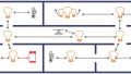
Another major benefit of RS-485 is that several encoders can all be connected to one bus (Figure 4). For implementations based on RS-485 technology, the AMT21 encoder provides a solution. Its default protocol of eight data bits, no parity, and one stop bit works by having the two lower bits define the encoder command with the other 6 bits used as an encoder address. This means that up to 64 encoders can share the same bus — providing advantages in complex, large-scale implementations. AMT21 encoders can also respond to positioning requests from the host within a 3µs period.

Figure 4. An example of an RS-485 configuration featuring multiple encoders connected to the host
Data transported via SSI is synchronized by the transmitter and receiver both referencing a common clock signal. This simplex one-way communication protocol relies on differential signaling and presents a very cost-effective interface solution. It can handle similar interconnect lengths to SPI and has comparable noise performance characteristics too.
CUI Devices’ AMT23 Series offers a solution in situations where SSI is the chosen interface. CUI Devices’ variation of a standard SSI protocol comes with a three-wire SSI interface incorporating a chip-select connection, which streamlines installation and simplifies the interface between host and encoders. The chip-select feature enables the host to activate specific individual encoders on the bus, while the encoder responds by simply putting position data on the bus.

Figure 5. The three-wire SSI configuration with chip select feature
Conclusion
Through the expansive portfolio of capacitive absolute encoders supplied by CUI Devices, and the array of interface technologies that these units support, engineers will be able to find a solution that matches their particular application requirements. In situations where there may be lengthy connection distances involved or noise levels need to be mitigated, it will be advisable for an RS-485 interface to be utilized.
If a straightforward implementation is a priority, then an encoder with SPI interfacing functionality is a good option. This is bolstered by the fact that it is supported by MCUs from a multitude of different semiconductor vendors. When the system deployment must be as streamlined as possible, with costs kept to a minimum and very little space taken up, then is SSI might be the way to go.