Facebook
 Google
 GitHub
 Linkedin
DIP Switches: Understanding the Basics
DIP switches come in many forms and offer an array of configurations, sizes, switching mechanisms, and power ratings. This article will help equip designers to select the best models for their designs.
In its most basic form, a dual in-line package (DIP) switch consists of multiple switches in a single unit, usually alongside each other in a line, as shown in Figure 1.
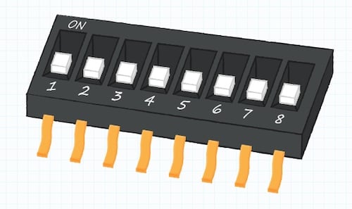
Figure 1. A common DIP switch configuration.
DIP switches are electromechanical devices that must be actuated manually to set their functionality. DIP switches are usually mounted to a PCB or breadboard and used to configure an electronic device between operating modes.
DIP switches are one of the workhorses of electronics design. They provide a reliable, flexible, and cost-effective way to configure equipment after manufacturing, either by the original equipment manufacturer or by the end customer.
Poles and Throws
A key specification of DIP switches is the number of poles and throws:
- Poles identify the number of inputs to the switch.
- Throws define how many different outputs each input can be connected to.
Single-Pole, Single-Throw
Figure 2 illustrates a single-pole, single-throw (SPST) switch. It is a single-pole switch because it only has one input at left. It is a single-throw switch because it only has one output at the right to which the pole can connect.

Figure 2. A single-pole, single-throw (SPST) switch.
This is a fundamental type of switch in electrical circuit design. It operates as a binary control element, effectively toggling a circuit between two states:
- Open: breaks the circuit and halts current flow.
- Closed: completes the circuit and permits current to flow.
Single-Pole, Double-Throw
The next step up in complexity is the single-pole, double-throw (SPDT) switch, in which a single input can connect to two possible outputs (Figure 3).

Figure 3. A single-pole, double-throw (SPDT) switch.
Rather than turning the current flow off, it simply redirects the current to a different circuit.
Double-Pole, Double-Throw
The double-pole, double-throw (DPDT) switch shown in Figure 4 can connect each of its two inputs to two independent outputs.

Figure 4. In a double-pole, double-throw (DPDT) switch, both inputs change at once.
The two inputs are mechanically interconnected, so that they both change state together.
While SPST, SPDT, DPST, and DPDT are the most common switch configurations, there is no theoretical limit to how many poles and throws a switch can have.
Normally Open or Normally Closed?
Another decision that needs to be made when selecting a DIP switch is the default (normal) state of the circuit. There are two options:
- Normally open (NO): the default state is an open circuit. It completes a circuit when actuated.
- Normally closed (NC): the default state is a closed circuit that conducts. It breaks a circuit when actuated.
Actuator Types
There are many forms and functions of DIP switches. In this section, we will discuss three of the most popular DIP switch actuator types:
- Slide
- Piano
- Rotary
Slide DIP Switches
Figure 5 is an example of an 8-position slide DIP switch. These SPST switches can be closed or open (on or off, 1 or 0).
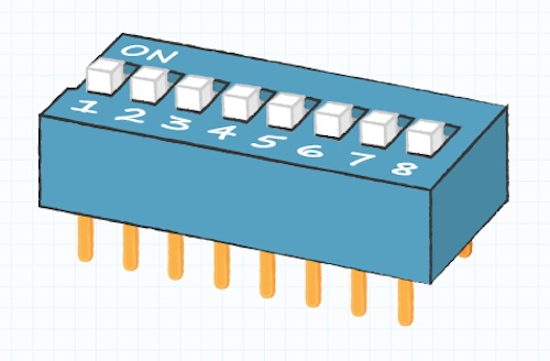
Figure 5. Slide DIP switch.
A three-position slide DIP switch adds a neutral central actuator position and a contact at each end to operate as an on/off/on switch.
Piano DIP Switches
Piano DIP switches have actuators mounted vertically, as shown in Figure 6. They are switched by the vertical motion of the actuator, similar to piano keys, hence the name.
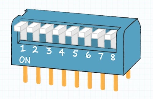
Figure 6. Piano DIP switch.
Rotary DIP Switches
Rotary DIP switches have an actuator that is turned to set the switch’s output (Figure 7). A four-output-pin rotary DIP switch can encode 16 binary values on its outputs or be used as a single pole device with four throws.
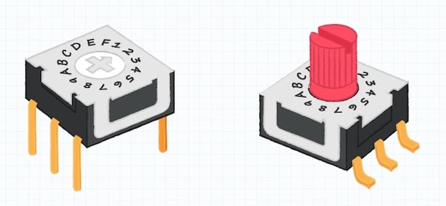
Figure 7. Two rotary DIP switch examples. The switch on the left is actuated by a small screwdriver or tool, while the switch on the right could be actuated by hand.
A 16-position rotary DIP switch utilizes a hexadecimal code to define specific output combinations. This code includes numbers from 0 to 9 and letters from A to F, as shown in Figure 8.

Figure 8. Hexadecimal code chart example for a 16-position rotary DIP switch.
Other DIP Switch Specifications
DIP switch specifications go beyond the form factor. Manufacturers’ datasheets can provide essential performance and specification information to help designers make informed choices. Some of the key specifications to keep in mind include:
- Number of switches: A DIP switch package commonly supports from 1 to 16 individual switches. Eight-position versions are popular for encoding the 256 binary values that can be expressed in an eight-bit byte.
- Mounting style: usually surface-mount for use on PCBs or through-hole for use on breadboards.
- Termination style: including gull-wing, angled gull-wing, J-hook gull-wing, PC pin, and crimped PC pin approaches, to allow for different mounting options.
- Voltage rating: from 2.4 to 50 VDC. This may be listed as two specifications: the maximum voltage the device can safely handle during switching and a higher non-switching voltage for when the actuator is stationary.
- Current rating: usually from 10 to 200 mA, which represents the maximum current through the switch.
- IP rating: describes the extent to which DIP switches can resist dust and moisture.
All these specifications need to be carefully considered if the DIP switch is to do its job properly within the target design. Otherwise, the DIP switch may have problems like electrical arcing or contact welding during switching.
Applications of DIP Switches
DIP switches have been around for years in garage door openers, remote controls, and configuring PC expansion cards and motherboards. They identify the configuration of industrial equipment without having to turn it on, saving operators time, money, and manpower.
DIP switches have even found new potential uses in IoT devices for preconfiguring or reprogramming a device before it gets installed into a smart home or factory.
As these applications show, DIP switches are a tremendously useful and flexible part of any electronic designer’s arsenal due to their simplicity and low cost. With a basic understanding of their various forms and specifications, designers can be better equipped to select the proper model for their design.
To learn more, Same Sky’s Fundamentals of Switches blog has additional details on switch functions and common switch types. You can also check out our DIP switch selection guide for further aid in device selection.
All images used courtesy of Same Sky.