Facebook
 Google
 GitHub
 Linkedin
High Definition, Low Delay, SDR-Based Video Transmission in UAV Applications
Integrated RF agile transceivers are not only widely employed in software-defined radio (SDR) architectures in cellular telephone base stations, such as multiservice distributed access system (MDAS) and small cell, but also for wireless HD video transmission for industrial, commercial, and military applications, such as unmanned aerial vehicles (UAVs).
Integrated RF agile transceivers are not only widely employed in software-defined radio (SDR) architectures in cellular telephone base stations, such as multiservice distributed access system (MDAS) and small cell, but also for wireless HD video transmission for industrial, commercial, and military applications, such as unmanned aerial vehicles (UAVs).
This article will examine a wideband wireless video signal chain implementation using the AD9361/AD93642,3 integrated transceiver ICs, the amount of data transmitted, the corresponding RF occupied signal bandwidth, the transmission distance, and the transmitter’s power. It will also describe the implementation of the PHY layer of OFDM and present hopping frequency time test results to avoid RF interference. Finally, we will discuss the advantages and disadvantages between Wi-Fi and the RF agile transceiver in wideband wireless applications.
The Signal Chain
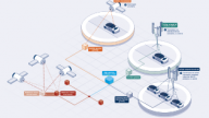
Figure 1 illustrates the simplified wireless video transmission scheme using the AD9361/AD9364 and a BBIC. The camera captures the image and transmits video data to a baseband processor via Ethernet, HDMI, USB, or another interface. Image coding/decoding can be handled by hardware or the FPGA. The RF front includes the switcher, LNA, and PA to the programmable integrated transceiver.

Figure 1. Wireless video transmission diagram.
How Much Data Needs to be Transmitted?
Table 1 shows the significant size difference between the uncompressed and compressed data rates. By using high efficiency video coding (HEVC), also known as H.265 and MPEG-H Part 2, we can decrease the data rate and save bandwidth. H.264 is currently one of the most commonly used formats for the recording, compression, and distribution of video content. It presents a huge step forward in video compression technology and is one of several potential successors to the widely used AVC (H.264 or MPEG-4 Part 10).

Table 1 summarizes the uncompressed and compressed data rates in different video formats. Assumptions include a video bit depth of 24 bits and a frame rate of 60 fps. In the 1080p example, the data rate is 14.93 Mbps after compression, which then can be easily handled by the baseband processor and the wireless PHY layer.
| Format | Horizontal Lines | Vertical Lines | Pixels | Uncompressed Data Rate (Mbps) | Compressed Data Rate (Mbps) Compressed Ratio = 200 |
| VGA | 640 | 480 | 307,200 | 442 | 2.2 |
| 720p | 1280 | 720 | 921,600 | 1328 | 6.64 |
| 1080p | 1920 | 1080 | 2,073,600 | 2986 | 14.93 |
| 2k | 2048 | 1152 | 2,359,296 | 3400 | 17.0 |
| 4k | 4096 | 2160 | 8,847360 | 12,740 | 63.7 |
Signal Bandwidth
The AD9361/AD9364 support channel bandwidths from <200 kHz to 56 MHz by changing the sample rate, digital filters, and decimation. The AD9361/AD9364 are zero-IF transceivers with I and Q channels to transmit the complex data. The complex data includes real and imaginary parts, corresponding to I and Q respectively, which locate at the same frequency bandwidth to double the spectrum efficiency when compared to a single part. The compressed video data can be mapped to the I and Q channels to create constellation points, which are known as symbols. Figure 2 shows a 16 QAM example where each symbol represents four bits.

Figure 2. 16 QAM constellation.4

Figure 3. I and Q digital waveform from the constellation.4

Figure 4. Pulse shaping filter response.4
For a single-carrier system, the I and Q digital waveform needs to pass through a pulse-shaping filter before the DAC in order to shape the transmitted signal within a limited bandwidth. An FIR filter can be used for pulse shaping, and the filter response is illustrated in Figure 4. In order to maintain the fidelity of the information, there is a minimum signal bandwidth corresponding to the symbol rate. And the symbol rate is proportional to the compressed video data rate as shown in the equation below. For the OFDM system, the complex data should be modulated to the subcarriers using the IFFT, which also transmits the signal in a limited bandwidth.

The number of bits transmitted with each symbol depends on the modulation order.

Figure 5. Modulation order.
The occupied signal bandwidth is given by,
.jpg)
In which α is the filter bandwidth parameter.
From the previous formulas we can deduce this equation,

So we can calculate the RF occupied signal bandwidth as summarized in Table 2.
| Format | Compressed Data Rate (Mbps) | QPSK (Signal BW, MHz | 16 QAM (Signal BW, MHz) | 64 QAM (Signal, BW, MHz) |
| VGA | 2.2 | 1.375 | 0.6875 | 0.4583 |
| 720p | 6.6 | 4.1250 | 2.0625 | 1.3750 |
| 1080p | 14.9 | 9.3125 | 4.6563 | 3.1042 |
| 2k | 17.0 | 10.6250 | 5.3125 | 3.5417 |
| 4k | 63.7 | 39.8125 | 19.9063 | 13.2708 |
The AD9361/AD9364, with up to 56 MHz signal bandwidth, support all the Table 2 video format transmissions and even higher frame rates. Higher order modulation occupies smaller bandwidth and the symbol represents more information/bits, but a higher SNR is needed to demodulate.
The Transmission Distance and the Transmitter Power
In applications such as UAVs, the maximum transmission distance is a critical parameter. However, it is equally important that communication not be cutoff even at a limited distance. Oxygen, water, and other obstacles (except for free space attenuation) can attenuate the signal.
Figure 6 shows the wireless communication channel-loss model.

Figure 6. Wireless communication channel loss model.5
Receiver sensitivity is normally taken as the minimum input signal (Smin) required to demodulate or recover the information from the transmitter. After getting the receiver sensitivity, the maximum transmission distance can be calculated with some assumptions, as shown here:

- (S/N)min is the minimum signal-to-noise ratio needed to process a signal
- NF is the noise figure of the receiver
- k is Boltzmann’s constant = 1.38 × 10⁻²³ joule/k
- T0 is the absolute temperature of the receiver input (Kelvin) = 290 K
- B is the receiver bandwidth (Hz)
The parameter (S/N)min depends on the modulation/demodulation order. With the same SNR, lower order modulation gets a lower symbol error, and with the same symbol error, higher order modulation needs higher SNR to demodulate. So when the transmitter is far away from the receiver, the signal is weaker and the SNR is not able to support the high order demodulation. In order to keep the transmitter online and maintain a video format with the same video data rate, the baseband should use lower order modulation at the expense of increasing bandwidth. This helps ensure the received images are not blurred. Fortunately, software-defined radio with digital modulation and demodulation offers the capability to change the modulation. The previous analysis is based on the assumption that the transmitter RF power is constant. While greater RF transmitting power with the same antenna gain will reach a more distant receiver with the same receiver sensitivity, the maximum transmitting power should comply with FCC/CE radiation standards.
In addition, the carrier frequency will have an influence on the transmission distance. As a wave propagates through space, there is a loss due to dispersion. The free space loss is determined by

In which the R is the distance, λ is the wave length, f is the frequency, and C is the speed of light. Therefore, the larger frequency will have more loss over the same free space distance. For example, the carrier frequency at 5.8 GHz will be attenuated by more than 7.66 dB as compared to 2.4 GHz over the same transmission distance.
RF Frequency and Switching
The AD9361/AD9364 have a programmable frequency range from 70 MHz to 6 GHz. This will satisfy most NLOS frequency applications, including various types of licensed and unlicensed frequencies, such as 1.4 GHz, 2.4 GHz, and 5.8 GHz.
The 2.4 GHz frequency is widely used for Wi-Fi, Bluetooth, and IoT short-range communication, making it increasingly crowded. Using it for wireless video transmission and control signals increases the chances for signal interference and instability. This creates undesirable and often dangerous situations for UAVs. Using frequency switching to maintain a clean frequency will keep the data and control connection more reliable. When the transmitter senses a crowded frequency, it automatically switches to another band. For example, two UAVs using the frequency and operating in close proximity will interfere with each other’s communications. Automatically switching the LO frequency and reselecting the band will help maintain a stable wireless link. Adaptively selecting the carrier frequency or channel during the power-up period is one of the excellent features in high-end UAV.
Frequency Hopping
Fast frequency hopping, which is widely used in electronic countermeasures (ECM), also helps avoid interference. Normally if we want to hop the frequency, the PLL needs to relock after the procedure. This includes writing the frequency registers, and going through VCO calibration time and PLL lock time so that the interval of the hopping frequency is approximate to hundreds of microseconds. Figure 7 shows an example of hopping transmitter LO frequency from 816.69 MHz to 802.03 MHz. The AD9361 is used in normal frequency changing mode and the transmitter RF output frequency jumps from 814.69 MHz to 800.03 MHz with a 10 MHz reference frequency. The hopping frequency time is tested by using the E5052B as shown in Figure 7. The VCO calibration and PLL lock time is about 500 µs according to the Figure 7b. The signal source analyzer E5052B can be used to capture the PLL transient response. Figure 7a shows the wideband mode of transient measurement, while Figure 7b and 7d provide significantly fine resolution in frequency and phase transient measurement with frequency hopping.6 Figure 7c shows the output power response.

Figure 7. Hopping frequency from 804.5 MHz to 802 MHz with 500 µs.
500 µs is a very long interval for the hopping application. However, the AD9361/AD9364 include a fast lock mode that makes it possible to achieve faster than normal frequency changes by storing sets of synthesizer programming information (called profiles) in the device’s registers or the baseband processor’s memory space. Figure 8 shows the test result by using the fast lock mode to implement the hopping frequency from 882 MHz to 802 MHz. The time is down to less than 20 µs, according to the Figure 8d phase response. The phase curve is drawn by referring to the phase of 802 MHz. The SPI writing time and the VCO calibration time are both eliminated in that mode due to the frequency information and calibration results being saved in profiles. As we can see, Figure 8b shows the fast frequency hopping capability of the AD9361/AD9364.

Figure 8. Hopping frequency from 882 MHz to 802 MHz within 20 µs in fast lock mode.
Implementation of the PHY Layer--OFDM
Orthogonal frequency division multiplexing (OFDM) is a form of signal modulation that divides a high data rate modulating stream onto many slowly modulated narrow-band close-spaced subcarriers. This makes it less sensitive to selective frequency fading.
The disadvantages are a high peak to average power ratio and sensitivity to carrier offset and drift. The OFDM is widely applied in the wideband wireless communication PHY layer. The critical technology of the OFDM includes IFFT/FFT, frequency synchronization, sampling time synchronization, and symbol/frame synchronization. The IFFT/FFT should be implemented via FPGA in the fastest way possible. It is also very important to select the interval of the subcarriers. The interval should be large enough to withstand the mobility communication with Doppler frequency shift and small enough to carry more symbols within the limited frequency bandwidth to increase the spectrum efficiency. COFDM refers to a combination of encoding technology and OFDM modulation. COFDM with its high resistance of signal attenuation and forward error correcting (FEC) advantages can send video signals from any moving object. The encoding will increase the signal bandwidth but it is usually worth the trade-off.
By combining the model-based design and automatic code generation tools from MathWorks with the powerful Xilinx Zynq SoCs and Analog Devices integrated RF transceivers, SDR system design, verification, testing, and implementation can be more effective than ever, leading to higher performance radio systems and reducing the time to market.7
What are the Advantages over Wi-Fi?
Drones equipped with Wi-Fi are very easy to connect to a cell phone, laptop, and to other mobile devices, which make them very convenient to use. But for wireless video transmission in UAV applications, the FPGA plus AD9361 solution offers many advantages over Wi-Fi. First of all, in the PHY layer, agile frequency switching and fast hopping of the AD9361/AD9364 help avoid interference. Most integrated Wi-Fi chips also operate on the crowed 2.4 GHz frequency band with no frequency band reselection mechanism to make the wireless connection more stable.
Secondly, with the FPGA plus AD9361 solution, transmission protocol can be defined and developed flexibly by designers. Wi-Fi protocol is standard and based on a two-way handshake with every packet of data. With Wi-Fi, each data packet has to confirm that a packet was received and that all 512 bytes in the packet were received intact. If one byte is lost, the whole 512-byte packet must be transmitted again.8 While this protocol ensures data reliability, it is complex and time-consuming to re-establish the wireless data link. The TCP/IP protocol will cause high latency that results in nonreal-time video and control, which can lead to a UAV crash. The SDR solution (FPGA plus AD9361) uses a one-way stream of data, which means the drone in the sky transmits the video signal like a TV broadcast. There is no time for resending packets when real-time video is the goal.
Additionally, Wi-Fi does not offer the proper level of security for many applications. By utilizing the encryption algorithm and user-defined protocol, the FPGA plus AD9361/AD9364 solution is far less susceptible to security threats.
Furthermore, the one way broadcast data stream delivers transmission distance capabilities two to three times that of Wi-Fi approaches.8 The flexibility from the software-defined radio capability enables digital modulation/demodulation adjustment to satisfy the distance requirements or and adjusting to changing SNR in complex space radiation environments.
Conclusions
This article illustrated the critical parameters of using an FPGA plus AD9361/AD9364 solution for high definition wireless video transmission implementation. With agile frequency band switching and fast-frequency hopping, it is possible to establish a more stable and reliable wireless link to resist the increasingly complex radiation in space and decrease the probability of a crash. In the protocol layer, the solution is more flexible, using a one-way transmission to reduce wireless establishment time and create a lower latency connection. In industrial and commercial applications such as agriculture, power-line inspection, and surveillance, stable, secure, and reliable transmissions are vital to success.
References
1 Software-Defined Radio Solutions from Analog Devices. Analog Devices, Inc.
2 AD9361 data sheet. Analog Devices, Inc.
3 AD9364 data sheet. Analog Devices, Inc.
4 Ken Gentile. Application Note AN-922, Digital Pulse-Shaping Filter Basics (PDF). Analog Devices, Inc.
5 Scott R. Bullock. Transceiver and System Design for Digital Communications, 4th edition. SciTech Publishing, Edison, NJ, 2014.
6 E5052B Signal Source Analyzer, Advanced Phase Noise and Transient Measurement Techniques. Agilent, 2007.
7 Di Pu, Andrei Cozma, and Tom Hill. “Four Quick Steps to Production: Using Model-Based Design for Software-Defined Radio.” Analog Dialogue, Volume 49, 2015.
8 John Locke. “Comparing the DJI Phantom 4’s Lightbridge vs. Yuneec Typhoon H’s Wi-Fi.” Drone Compares.