 Facebook
 Google
 GitHub
 Linkedin
Nine Factors to Consider for Board-Level Machine Vision Camera Integration
Leveraging board-level cameras offer a variety of benefits. To help identify the right mix of features and design elements, here are some factors to consider when selecting and designing in an embedded machine vision camera.
The ability to leverage machine-vision based artificial intelligence within a product requires the ability to design in a full-featured, board-level machine vision camera into a much smaller, powerful package, to provide greater flexibility from the cable to lens choices, in addition to reduced size for new products and systems. What is more, leveraging board-level cameras offer direct access to core camera components for easier heat dissipation, and can be leveraged across a variety of uses: medical diagnostics, metrology, robotics, embedded vision, packaging and print inspection, handheld scanners, benchtop labs and other space-constrained systems.

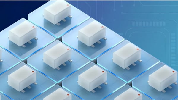
Figure 1. Board-level cameras can be used in a variety of ways but there are design factors to consider.
But choosing the right embedded vision camera is another question entirely. In some cases, an off-the-shelf camera will work fine, as board-level cameras can often be more susceptible to electrostatic discharge (ESD) and physical damage, let alone the fact this option typically requires more design effort, design expertise, and potentially more expense.
To help identify the right mix of features and design elements required for a given project, there are nine key factors to consider when selecting and designing in an embedded machine vision (mv) camera:
- Feature set and form factor
- Lens mounting
- Case design for rapid prototyping
- Thermal management
- Interfaces and connectors
- MIPI cameras versus standard MV cameras
- Electromagnetic compatibility
- Off-the-shelf boards
- Deep learning CPU versus GPU performance
Let's look at each of these factors in more detail.
Feature Set and Form Factor
Balance the right features with the physical footprint of the camera, including the use of compact GPIO and interface connectors to save space. Often, the board-level variants of many full-featured MV cameras are simply standard cameras with their cases removed, which needs to be factored into the design. Furthermore, board-level cameras provide for greater flexibility to customize the FPC cable length along with the option of a shared cable design file.
Lens Mounting
With no fixed lens mount, board-level cameras give designers the freedom to select optics other than the standard C, CS or S-Mount lenses commonly used in the MV industry.
Enabling the lens mount to be integrated into another product part, or even molding a lens mound directly into a product’s housing, can further reduce costs by simplifying manufacturing and assembly. However, if the standard mount lenses are preferred, use the S mount for sensors one-third of an inch or smaller with low resolution, such as 2MP. The CS mount is typically recommended for sensors on the order of one-third to one-inch in size, and the C mount for sensors one-inch or larger.
Case Design for Rapid Prototyping
Board-level cameras often do not include cases, but in applications where the camera will not be integrated into a product, and thus camera internals are left exposed to the elements, a case might be necessary.
For rapid prototyping, take advantage of existing CAD models and 3D printers, or use generic plastic cases that can encapsulate the camera and mount the camera in place using spacers and mounting brackets.
Thermal Management
With no case, high-performance board level cameras may have additional design requirements to ensure they are operating within their recommended temperature range. To avoid damaging the camera, the reported temperature of the camera needs to stay below the maximum temperature of key components, such as the sensor/FPGA. In such cases, providing adequate heatsinking is key. The recommended option is the use of thermal pastes or putty versus thermal pads to minimize board stress on the camera.
Interfaces and Connectors
USB 3.1 Gen 1 is an ideal interface for embedded systems. Flexible printed circuit cables can support USB 3.1 Gen 1 over cable lengths of up to 30m. However, one potential drawback of USB 3.1 interface is its high-frequency signal can cause interference on wireless devices up to 5 GHz. In this case, a GigE interface might work or the more complex MIPI CSI interface.
MIPI Cameras Versus Standard MV Cameras
The aforementioned MIPI cameras are less expensive compared to standard MV cameras, potentially up to 50 percent or more, but that reduced price includes fewer features primarily due to the lack of FPGA.
The typical MIPI cameras generally offers raw sensor output with little to no image processing or enhancement (e.g., flat field correction, blemish pixel correction, fixed pattern noise correction, etc.), requiring additional work to improve the image quality. Most importantly, the MIPI generally requires the use of embedded systems that support MIPI cameras, while USB3/GigE MV cameras can be used on ARM boards and standard desktop PCs alike.
Electromagnetic Compatibility
Without the shielding provided by a case, the electromagnetic compatibility (EMC) of board-level cameras will be different than cased models. As these board-level cameras are embedded into other products or systems, the final product needs to be certified separately.
Off-the-Shelf Boards
Some vendors also develop their own carrier or arm carrier solutions for an embedded board. ARM processors and carrier board make it simpler for integrators to buy off-the-shelf solutions instead of requiring a custom board, to save time and money.
Depending on the requirements of the design, boards can be purchased and configured with up to four or more USB3 host controllers to stream from four USB3 cameras at full bandwidth.
Deep Learning CPU Versus GPU Performance
Deep learning algorithms run very slowly on regular processors compared to GPUs. Where quicker inferencing is a must, GPUs are the better option, even when images are first sent to the cloud for processing as inferencing in the cloud is typically the cost-conscious choice where edge computing isn’t mission-critical.
Another option to run deep learning inference on embedded systems is to use an inference-capable camera that can run the inference model on the camera itself, which can also help offload the processing requirements from the host system.
With these nine core factors in mind, integrating the right board-level MV with the appropriate feature set will hopefully become much easier, reducing designer headaches and design time while improving the overall product application.


Great article. One comment regarding the lenses paragraph. I would change the S-to-CS threshold from 1/3” to 1/2” and 2MP to 20MP. Many S-mount lenses can outperform CS mount lenses. For example, GoPro uses an S-mount configuration for their 1/2.3” 20MP board level camera. There are few 20MP+ CS mount lenses on the market because of the artificial back-focal length constraint which the mount imposes.
“use the S mount for sensors one-third of an inch or smaller with low resolution, such as 2MP. The CS mount is typically recommended for sensors on the order of one-third to one-inch in size, and the C mount for sensors one-inch or larger.”