Facebook
 Google
 GitHub
 Linkedin
Binary To BCD Conversions, With LED Display Driver
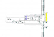
 Click to expand image
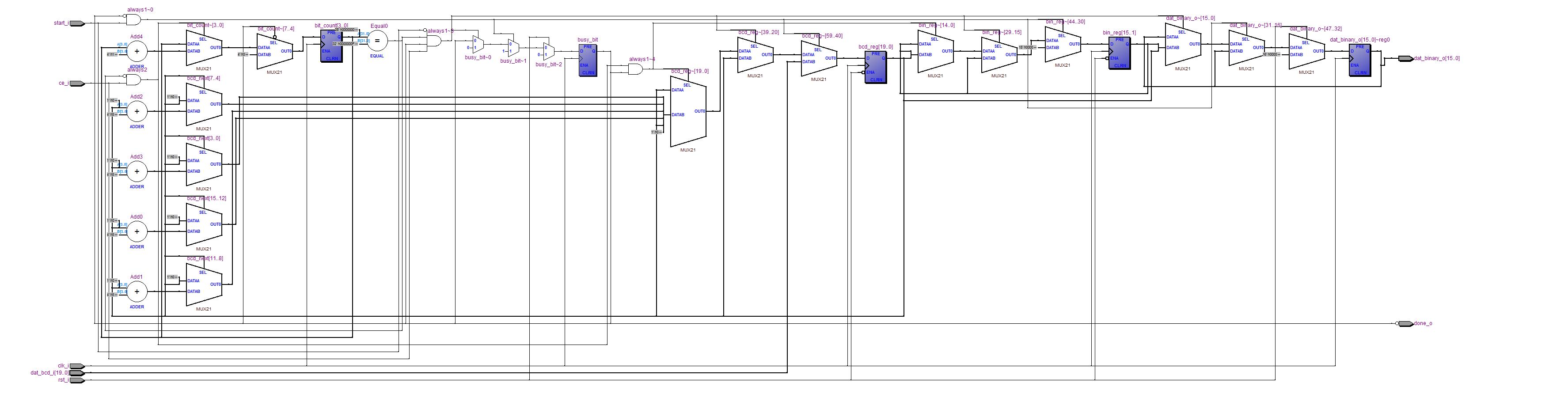
Details
Category: Arithmetic Core
Created: Nov 26, 2003
Updated: Nov 19, 2019
Language: Other
Other project properties
Development Status: Stable
WishBone compliant: No
WishBone version: n/a
License: n/a
Description
These cores provide a simple means of converting between binary and BCD in hardware. Written in Verilog, with parameters for the input and output widths, these simple cores illustrate the use of functions in Verilog for performing operations that are not easy to do any other way in a fully parameterized (scalable) block of logic.
There are two conversions: binary_to_bcd and bcd_to_binary. These operate serially, requiring one clock per binary bit used in the conversion.
The method used for the conversion from base 2 to base 10 is what I call a "binary coded decimal arithmetic shift right" (bcd_asr) and "binary coded decimal arithmetic shift left" (bcd_asl). It is a special bit shift that involves checking for the magnitude of each 4-bit "digit" along the way. When the magnitude is too great, a subtraction is performed, and a carry is generated for the next digit, which is then propagated down the entire string of digits. This method seems to work well for arbitrary size input and output words. Since the subtract/carry is performed during the shifting process, a carry never propagates further than one digit... so there is no clock speed penalty for longer conversions.
The method used in these cores for conversion should easily work for converting between any two numbering systems with EVEN BASES. So, for example, it could be modified to output octal or base 14 instead of BCD. But then, on a more practical note, who really uses those number bases in hardware anyway?
There is also a 7-segment multiplexed type LED display driver, which was used in testing these modules.
Features
- Modules completed, debugged and tested in SpartanII hardware.
- Hardware test environment source code provided.
- Parameterized Verilog, shows use of functions.
- Start and End signals used (easily Wishbone compatible.)
- Fully registered input and output.
- A lengthy commentary at the beginning of each Verilog source file describes how the particular module works, and what the parameters mean. This suffices for documentation, since no other design documentation is provided.
Status
- Project completed, debugged and tested in hardware, modules are considered stable and ready for use.
- Binary to BCD conversion, 16-bit binary to 5-digit BCD, consumes 45 slices in Xilinx SpartanII, reported 136MHz maximum operating speed (over 8 Million conversions per second).
- BCD to Binary conversion, 5-digit BCD to 16-bit binary, consumes 30 slices in Xilinx SpartanII, reported 116MHz maximum operating speed (over 7 Million conversion per second).
- Hardware test environment consumes 532 slices in Xilinx SpartanII, 48MHz clock speed used in testing (includes two converters, 16 registers, auto-baud rate serial hardware debugger, 7-digit multiplexed LED display driver).