
Energy Sharing—The Key to Preventing LED Drivers from Overheating?
Managing heat in LED drivers is a challenge when the device encounters a high input voltage, but the output voltage is low. In these cases, an “energy sharing” mechanism may be a solution.
LEDs exhibit an illumination rise time about two times faster than that of incandescent sources. They are more power-efficient, smaller in size, and offer a superior lifetime. That's what makes them so appealing to designers in the automotive industry.
To power an LED string, we need a current-regulated source. A source with constant voltage cannot produce consistent lighting because the voltage across the LED string can vary with the number of LEDs and the ambient temperature; the LED forward voltage decreases by 2 mV/°C, a characteristic that will require attention. An LED driver is basically a current-regulated source with some useful features for powering LEDs.
In this article, we’ll take a look at the BD18337EFV-M, which is a recently-released LED driver manufactured by ROHM Semiconductor. The new LED driver is meant for automotive applications. Perhaps, the most important characteristic of this LED driver is its thermal management capability. We’ll look at this feature in great detail and compare the new device with conventional solutions.
Typical Application Schematic of the New LED Driver
A typical application schematic of the BD18337EFV-M (and its sister product BD18347EFV-M) is shown in Figure 1. As depicted in this figure, the new device is a four-channel driver.
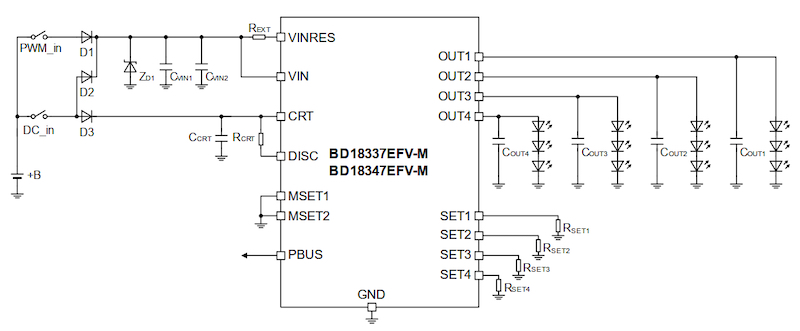
Figure 1. Typical application schematic of BD18337EFV-M. Image used courtesy of ROHM Semiconductor
Each channel can provide a fixed current up to 150 mA to power its LED string. The output current accuracy is ±5%. The current sourced by each channel is determined by the resistor connected to the corresponding SET pin and is given by the following equation:
$$I_{OUTx} = \frac {K_{SET}}{R_{SETx}}$$ (in Amperes)
where $$K_{SET}$$ is the output current setting coefficient with a typical value of 1800 and $$R_{SETx}$$ is the current setting resistor. The measured output current versus the resistor value is plotted below:
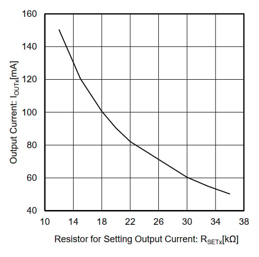
Figure 2. Output current vs. resistor value. Image used courtesy of ROHM Semiconductor
Input Voltage Range
The supply voltage of a vehicle can have large variations. For example, while the car battery voltage should be typically about 12 V, it can go as low as 6 V at times. These supply fluctuations make designing automotive electronics challenging.
The BD18337EFV-M supports a wide input range from 5.5 V to 20 V. Although the device supports this voltage range, we still need to provide a sufficiently high input voltage depending on the number of LEDs that are powered by each channel (N) and the total output current of the driver $$I_{OUTx - Total}$$.
The equation for the minimum input voltage is given below:
$$V_{IN} \geq N \times V_{Forward–LED} + V_{DR} + R_{VIN–VINRES} \times I_{OUTx–Total}$$
If we consider only the first term on the right hand, we observe that the input voltage cannot be less than the voltage drop across the LED string ($$N \times V_{Forward-LED}$$). For more details about this equation, please refer to the device's datasheet.
Energy Sharing Control
As discussed above, the BD18337EFV-M supports a wide input range from 5.5 V to 20 V.
This wide input range can lead to large power consumption in the device in applications where a high input voltage is applied to the device and the output is at a relatively low voltage. As an example, consider the simplified schematic shown in Figure 3.
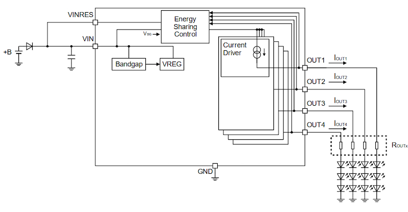
Figure 3. Simplified schematic of BD18337EFV-M. Image (modified) used courtesy of ROHM Semiconductor
Assume that the input voltage is 18 V and the four output channels are at 6 V, i.e., $$V_{OUTx}$$ = 6 V for x=1 to 4.
What would be a rough estimate for the power burned in the driver if the total output current is 400 mA ($$I_{OUTx-Total} = I_{OUT1} + I_{OUT2} + I_{OUT3} + I_{OUT4} = 400 mA$$)?
Assuming that the current enters the device only through the VIN pin and exits only through the four outputs shown above, we can conclude that a voltage drop of 18 V - 6 V appears between the input and output pins.
Considering the total current that goes through the device, we can calculate the power burned in the device as:
$$P_{IC}$$ = (18 - 6) V x 400 mA = 4.8 W
This amount of power can increase the IC internal temperature to an unacceptable level depending on the thermal resistance of the package.
To solve this issue, the BD18337EFV-M employs an interesting technique referred to as “Energy Sharing Control” in the datasheet. The “Energy Sharing Control” dissipates the extra power that can overheat the device in an external resistor.
This external resistor should be placed between VIN and VINRES pins as shown in the following figure.
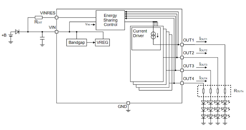
Figure 4. Output current settings of the BD18337EFV-M. Image used courtesy of ROHM Semiconductor
The “Energy Sharing Control” block monitors the output voltage of the channels and keeps the VINRES voltage within 2 V, the maximum output voltage (maximum $$V_{OUTx}$$). Hence, the extra power can be dissipated by the $$R_{EXT}$$ resistor when the input voltage is much larger than the output voltage.
The datasheet provides several plots to illustrate how the total power is shared between the driver IC and the external resistor. For example, the following figure shows an experiment where the four output channels are at 6 V ($$V_{OUTx}$$ = 6 V for x=1 to 4), the total output current is 400 mA and the input voltage is swept from 5 V to 20 V.

Figure 5. Power consumption across the IC and REXT when the total output current is 400 mA and the input voltage is swept from 5 V to 20 V. Image used courtesy of ROHM Semiconductor
The figure plots the driver power (Pc_IC) and the external resistor power (Pc_$$R_{EXT}$$) for three different values of the external resistor. With $$R_{EXT}$$ = 15 Ω, we have Pc_IC ≈ 2.4 W and Pc_$$R_{EXT}$$ ≈ 2.6 W.
As you can see, almost half of the total power is consumed by the external resistor; the external resistor reduces the heat generated by the IC. Figure 6 shows a measurement to verify the efficiency of the energy sharing mechanism.

Figure 6. Measurement results of energy sharing. Image used courtesy of ROHM Semiconductor
In this experiment, the input voltage is changed from 9 V to 13.5 V to 16 V while the output voltage is 6.25 V. The external resistor $$R_{EXT}$$=31 Ω is created by two 62 Ω resistors in parallel.
To better understand the advantages of the energy sharing mechanism discussed above, let’s take a look at another LED driver that attempts to dissipate the unnecessary power in external resistors.
Another LED Driver With a Similar Energy Sharing Mechanism
The E522.90/91/92/93 family from Elmos Semiconductor AG supports a thermal management option similar to that employed by the BD18337EFV-M. The typical application circuit for the E522.90/91/92/93 family is shown below.
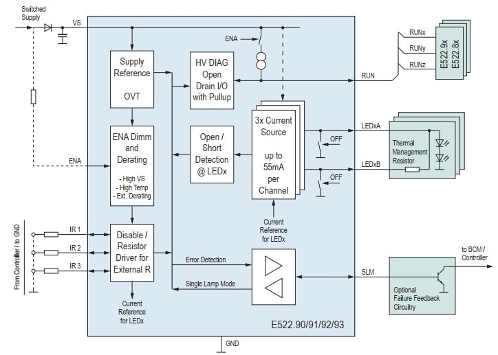
Figure 7. Typical application circuit for E522.90/91/92/93. Image used courtesy of Elmos AG
The input voltage of this driver family ranges from 5 V to 25 V. An excessive amount of power will be dissipated by the driver in applications where a high input is utilized but the output is at a relatively low voltage.
To handle the excessive amount of power dissipated in the driver, the E522.90-93 device family utilizes two output pins, LEDxA and LEDxB, per output channel (depicted on the right side of the above figure). The device attempts to regulate the sum of the currents sourced by these two output pins.
The channel current will be primarily supplied by the LEDxB output. This pin is connected to the LED string through a “Thermal Management Resistor.” Hence, the LEDxB pin will be at a higher voltage relative to the voltage applied to the LED string. And, some of the extra power can be dissipated in the external resistor rather than the driver.
However, the voltage drop across the resistor can limit the voltage headroom for large output currents. That’s why the LEDxB will supply the current as long as we have sufficient voltage headroom. When the current in the LEDxB output drops below the target value due to the voltage headroom limitation, the LEDxA output will be activated to supply the rest of the current so that the sum of the currents remains regulated.
How Does the New “Energy Sharing Control” Affect Board Area and Design Load?
While the power management of the E522.90/91/92/93 family requires two output pins per channel, the energy sharing mechanism of the BD18337EFV-M uses a single pin to dissipate the extra power in an external resistor. This can reduce the board size by implementing a four-channel high-current driver in a compact 16-pin package.
Besides, the new device can simplify the thermal design because the power management of the four output channels is achieved by a single external resistor. It seems that the new LED driver can reduce the board area and simplify thermal management. Though, I am wondering if there is a use case where independent thermal management of the channels can be helpful. If there is any such application, we might prefer a device from the E522.90/91/92/93 family to the recently-released LED driver from ROHM Semiconductor.
Conclusion
Thermal management of an LED driver becomes challenging particularly in applications where a high input voltage is applied to the device and the output voltage is at a relatively low voltage. In these cases, an energy sharing mechanism similar to that employed in the BD18337EFV-M from ROHM Semiconductor or the E522.90/91/92/93 family from Elmos Semiconductor can be employed.
To see a complete list of my articles, please visit this page.


The Rohm device needs a single external resistor for power management. But on the IR-images you see this resistor split in two parts. So the difference to Elmos device becomes smaller. Also the Elmos device allows the adjustment of this resistor to LEDs with different forward voltages or different number of LEDs.