Facebook
 Google
 GitHub
 Linkedin
High-Frequency Upconversion and Downconversion: A New RF Mixer from Linear Technology
New RF devices such as the LTC5553 help you to maintain high performance even at very high frequencies.
New RF devices such as the LTC5553 help you to maintain high performance even at very high frequencies.
RF mixers perform frequency translation; the equivalent operation in the mathematical realm is multiplication. Mixing is a ubiquitous task in RF systems—moving signals back and forth between higher and lower frequencies is a fundamental aspect of wireless communication. Many RF architectures rely upon an IF signal, where IF refers to the fact that the signal’s frequency is somewhere between the RF frequency and the baseband frequency. In other words, it’s an “intermediate frequency.” (Those of you who are annoyed by the subtle redundancy of the term “ATM machine” will perhaps cringe when you hear someone referring to “the IF frequency.” I don’t approve either but it’s hard to avoid sometimes.)
A standard mixer application is translating a signal between the RF frequency and the IF frequency (you were warned!). In both cases one of the input signals is the local oscillator (LO). For the receive chain, the other input is the RF signal and the output is the IF signal. For the transmit chain, the other input is the IF signal and the output is the RF signal. The following diagram conveys this situation:

Diagram taken from the LTC5553 datasheet.
Active vs. Passive
A mixer can be either active or passive. An active mixer involves transistors arranged in such a way as to provide multiplication and gain. A passive mixer performs only multiplication (i.e., no gain) and can be something as simple as a FET connected as a series switch (i.e., half of a transmission gate).
The LTC5553 is a passive mixer. I don’t know anything about the internal details of this device, but I strongly suspect that the actual mixer portion is much more complicated than a single FET. There are various pros and cons associated with active and passive mixers. Passive mixers generally achieve better high-frequency performance, and that helps to explain why the LTC5553 can support frequencies up to 20 GHz.
Double-Balanced?
If you read the part description, you will also notice that this is a “double-balanced” mixer. RF terminology sometimes seems designed to scare away those who have not been initiated into the RF club; don’t be intimidated (at least not in this case. . . ). “Balanced” is simply another way of referring to a differential signal. Recall that a mixer has two inputs; if one of the input ports is differential and the other is single-ended, it’s a single-balanced mixer (i.e., it has one balanced input port). If both inputs are differential, it’s a double-balanced mixer. Now take a look at the block diagram for the LTC5553, and you will likely declare me a fool.

Diagram taken from the datasheet.
I have just stated that the LTC5553 is a double-balanced mixer, and I have explained that a double-balanced mixer has two differential input ports. Yet the diagram clearly shows that the LTC5553 has not two, not one, but zero differential input ports.
If we look a little more carefully, though, we notice that the mixer itself—i.e., the mixer element within the LTC5553 IC—does indeed have two differential inputs (and one differential output). The LTC5553 can describe itself as a double-balanced mixer while accepting single-ended inputs because it incorporates a single-ended-to-differential amplifier (for the LO) and a balun (for the other signals). This is significant because one of the typical disadvantages of a double-balanced mixer is that it requires external magnetics for the single-ended-to-differential conversion, but in this case the baluns are integrated into the device. These integrated baluns are optimized for the device’s intended frequency ranges, and of course they simplify implementation of the LTC5553.
External Components
Few are needed, at least according to the “test circuit” given in the datasheet.

Diagram taken from the datasheet.
In fact, I count only three: two decoupling caps and a DC-blocking cap for the LO signal. This DC-blocking cap is always required, and keep in mind that the RF and IF inputs also need a DC-blocking cap if the RF or IF signal has a DC offset.
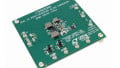
Eval Board
Designing RF printed circuit boards is not something I would describe as easy, and it’s not always a great way to evaluate a particular part. The issue is that inadequate performance could be due to PCB imperfections rather than the part itself. Thus, it’s handy when RF components, such as the LTC5553, offer a companion eval board.

Diagram taken from the datasheet.
Despite the difficulties of working with signals up in the gigahertz range, I think that you can still do quite a bit of meaningful development using various eval boards connected via high-quality RF cables.
If you have any tips related to using evaluation boards for RF testing or prototyping, feel free to share them in a comment.