Facebook
 Google
 GitHub
 Linkedin
Innovative Interconnects: The Future of Chiplet-based Processors?
Many of the world's largest chipmakers like AMD, Intel, and NVIDIA are investing in chiplets. But heterogeneous processors are not without their flaws.
In 1965, Gordon Moore postulated that the number of transistors on microchips would double roughly every two years. The past several decades have shown this to be an accurate prediction as more transistors are packed onto each newly-released chip and node sizes have shrunk dramatically.
Still, there is a limit to how small semiconductor node sizes can get without negatively impacting device functionality. According to MIT Technology Review, the semiconductor industry has acknowledged that process node size will stop shrinking soon—bringing an end to Moore’s Law as we know it.
One promising way to effectively sidestep this node size limit has been chip-level heterogeneous integration. This means connecting several specialized, smaller semiconductor devices within a package to create a system-in-package (SiP) instead of a system-on-chip (SoC). By splitting the functionality of a chip into smaller devices known as chiplets, semiconductor manufacturers can achieve higher yields than with monolithic SoCs.

Illustration showing chiplet-based IC. Image used courtesy of APEC
As chiplet-based processors, such as AMD’s Zen 2, have gained traction in recent years, industry research and development have focused on improving die-to-die interconnect capabilities in heterogeneous architectures.
The Rise of SiP Chiplet Architectures
In addition to improving yield, heterogeneous chiplet architectures also allow manufacturers to create optimized processors by combining different types of cores within a single package. For example, a heterogeneous mobile processor can have both high-performance, power-intensive cores and lower-performance, power-efficient cores on separate chiplets. This allows an operating system program known as the scheduler to determine which programs (threads) to dedicate to each type of core and optimize overall power and performance.

Flowchart showing how modern OS schedulers take advantage of heterogeneous CPU architectures. Image used courtesy of the University of Manchester
Even so, chiplet-based designs have their own technical challenges. One of the major hurdles with SiP chiplet architectures is building a die-to-die interconnect that is cost-effective, performant, and power-efficient.
Parallel Interconnects for Die-to-Die Comms
As in other systems, there are two broad types of physical layer die-to-die interconnects: parallel and serial. Parallel and serial interconnects both have important advantages and are used depending on the geometry of the SiP. In general, there are three types of SiP geometries: 2D, 2.5D, and 3D.

NASA's Electronic Parts and Packaging Program (NEPP) shows the progression of chiplet packaging. Image used courtesy of NASA
Historically, chiplet-based and SoC architectures have commonly used 2D package geometries. For such geometries, where two chiplets can be relatively far apart, serial SerDes PHY is generally used with clock and data transmitted using just one wire.
A SerDes is a serializer/deserializer system. The system takes in parallel clock and data signals from one chiplet, serializes it into a single wire, and transmits it at a very high data rate across a substrate to another chiplet. This is useful over longer transmission distances such as those in 2D geometry SiP systems because it eliminates timing skews between clock and data lines that occur in parallel interconnects. Timing skew in this context refers to the differences in arrival times of data and clock signals at the receiver due to propagation delay in the transmitting wire.

SerDes interconnect between two chiplets. Image used courtesy of Microchip Technology and NASA
However, SerDes interconnects come with a price: they generally consume more power because of the complex circuitry required to serialize data and clock and subsequently recover both signals at the receiver.
To solve this problem, semiconductor design firms have started work on 2.5D and 3D chiplet geometries that use parallel interconnects and interposers. Interposers allow chiplets to be stacked and greatly reduce the distance data and clock signals need to travel between chiplets. Additionally, interposers allow for very high-density parallel connections.

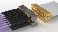
Parallel interconnect between two chiplets facilitated by high-density interposer. Image used courtesy of Microchip Technology and NASA
Because the 2.5D and 3D geometries reduce the distance between dies through vertical stacking, timing skew does not become as much of a problem as it would in 2D geometries. Therefore, parallel interconnects offer the best combination of power efficiency while still being able to match the bandwidth of the SerDes approach used in 2D geometries.
Furthermore, parallel interconnects can also achieve much lower-latency transmission since there is no longer any overhead associated with serialization, deserialization, encoding, and decoding as in SerDes systems. In fact, Intel has shown that its Advanced Interface Bus (AIB) standard has a much lower total delay (latency) compared to a SerDes system.

Table showing the lower latency of the AIB standard compared to SerDes systems. Image used courtesy of Intel
Standardizing a Protocol for Chiplet Interconnects
With the rise of high-performance computing and machine learning, the workloads that heterogeneous processors must handle have increased dramatically. As a result, a new protocol standard called Universal Chiplet Interconnect Express (UCIe) has been announced to help build an open chiplet ecosystem across the semiconductor industry. UCIe is a layered protocol that specifies a physical layer, a die-to-die adapter layer, and a protocol layer. It allows both 2D and 2.5D geometries for packaging, as shown in the image below.

UCIe layers and packaging options. Image used courtesy of the Universal Chiplet Interconnect Express
UCIe seeks to be both a power-efficient and cost-effective standard for use across the semiconductor industry and could play a critical role in future heterogeneous architectures.