Facebook
 Google
 GitHub
 Linkedin
Ultra-Low Jitter: A Programmable Oscillator with Internal EEPROM from Texas Instruments
The LMK61E07 is an I2C-controlled programmable variable frequency oscillator that can be used as an adjustable frequency source in computer networking, medical imaging, FPGA, and broadcast video applications.
The LMK61E07 is an I2C-controlled programmable variable frequency oscillator that can be used as an adjustable frequency source in computer networking, medical imaging, FPGA, and broadcast video applications.
I like things that are programmable—not only does it mean that I gain design flexibility that I never knew I needed, but it also means I get to make mistakes in new and exciting ways.
As an example, the datasheet of the LMK61E07 indicates that the digital phase-locked loop (PLL) “loss of lock detection circuit” can sense and report frequency error as small as “a single cycle skip”. I’m certain that if I used this IC in a circuit I designed, I would make heavy use of that feature on the very first spin. Somewhere around spin 4 or 5, and several hundred dollars poorer, I will have grown tired of that feature and finally create a design that no longer loses PLL lock when changing frequencies.
Inside the IC
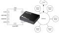
The clock section of this IC contains a 50 MHz crystal, a fractional phase-locked loop (PLL), and an integer-output divider tied to a differential output buffer. A perhaps overly simplified explanation is that it takes a very accurate crystal clock source and manipulates it to create a much, much faster, very stable oscillator. Then, it outputs a clock pulse after a certain number of oscillations have occurred.
Serial communication via I2C provides access to configuration registers and on-chip 100-write-cycle EEPROM that can control power-on defaults.

LMK61E07 Block Diagram from TI
Three Clock Output Options
Any quickly changing logic state will create electromagnetic radiation that can propagate to other locations in the circuit as unwanted interference. One technique to minimize that noise is with differential signaling—two identical-amplitude, identically timed, opposite-polarity signal lines in close physical proximity create electromagnetic fields that largely cancel each other out.
Once the signal reaches its destination, circuitry can filter noise that might have originated along the path and deliver a single clean clock pulse without swamping the rest of your circuit in clock-noise.

Image of a differential signal receiver from Jdc1197 [CC BY-SA 4.0]
The differential clock output of this device can be configured in one of three common ways. These topologies are provided to give designers options to interface whatever IC is being driven by the clock.
Low Voltage Positive Emitter-Coupled Logic (LVPECL)
This method allows clock outputs up to 1 GHz, but current consumption is higher than in the other two methods. LVPECL allows for faster rise and fall times at higher voltages, so it is less susceptible to noise and more likely to create it.

Image of LVPECL input/output topology from Microchip.
Low Voltage Differential Signaling (LVDS)
LVDS allows clock outputs up to 900 MHz; it uses lower transition voltages than the other two methods.

Image of LVDS input/output topology from Microchip.
High Speed Current Steering Logic (HCSL)
This method allows for clock outputs up to 400 MHz—the voltage swings on HCSL are close to what you’d see on LVPECL—however, HCSL is ground-referenced, as opposed to LVPECL, which is Vcc-referenced.

Image of high-speed current steering logic topology from Microchip.
Internal and Output Frequencies
The overall output range of this device appears to be $$f_{out}=10\;MHz−1000\;MHz$$ (according to chart 6.6). The datasheet provides equations to help designers determine the VCO frequency as well. I would personally like to have seen the datasheet authors come up with a more intuitive way of demonstrating the VCO frequency than the equations and ranges provided. An interactive webpage, or even a spreadsheet, would suffice. As it stands, there are a series of equations provided in the datasheet that designers can use to determine available VCO frequencies.
$$F_{VCO}=\frac{50 [MHz]\times\frac{1\;or\;2}{1\;or\;4}\times((1\;to\;4095)+\frac{0\;to\;4194303}{1\;to\;4194303})}{5\;to\;511}$$
Summary
This ultra-low-jitter programmable oscillator certainly might work in a software-defined radio, a television tuner, or an ultrasound machine. At $13.50 per unit (1k quantities) and $22 for single-unit quantities, I imagine it will only find a home in medium- to high-end equipment.