Facebook
 Google
 GitHub
 Linkedin
An ADC for Low-Power Data Acquisition Designs: A DC-to-204 kHz, Configurable ADC from Analog Devices
This article will look at some of the most important features of the AD7768-1, a new ADC from Analog Devices that is intended for low-power data acquisition (DAQ) designs.
This article will look at some of the most important features of the AD7768-1, a new ADC from Analog Devices that is intended for low-power data acquisition (DAQ) designs.
The AD7768-1 is a single-channel high-performance sigma-delta ADC which offers a programmable output data rate (ODR) up to 1024 kSPS. Many features of this ADC, such as the ODR value, power consumption, and input bandwidth, are programmable. Also, the device includes a number of built-in digital filters that allow you to choose the filter type and latency according to the requirements of a given application. This high level of flexibility, which is one of the most important features of the AD7768-1, gives us the opportunity to optimize the design for three parameters: input bandwidth, ODR, and power dissipation.
The AD7768-1 achieves a dynamic range of 108.5 dB at 256 kSPS; the input bandwidth is 110.8 kHz. This is achieved with $$\pm$$1.1ppm integral non-linearity, $$\pm$$30 $$\mu$$V offset error, and $$\pm$$30ppm gain error.
You could use the AD7768-1 for applications such as electrical test and measurement, acoustic research, and vital-signs monitoring. The functional block diagram of the device is shown below.

Functional block diagram of the AD7768-1. Image courtesy of Analog Devices.
In the rest of the article, we’ll briefly look at the important blocks of the above diagram.
Precharge Buffers
The analog inputs, Ain+ and Ain-, are connected to precharge buffers. These buffers decrease the analog input current of the ADC. Note that, based on the input bandwidth and power consumption considerations, we generally need an external amplifier to drive the ADC. The drive amplifier must be able to settle the analog inputs for a particular power mode of the ADC. The precharge buffers allow us to use a lower power and lower bandwidth drive amplifier. The following table from the device datasheet shows the benefits of the precharge buffers for a given drive amplifier and ADC power mode. As you can see, turning the precharge buffers on improves the THD by about 20 dB.

Table taken from the device datasheet.
Sigma-Delta ADC
The AD7768-1 uses a low noise, wide bandwidth 24-bit sigma-delta ADC. The modulator clock rate ($$f_{MOD}$$) is derived from a master clock signal (MCLK). As shown in the figure below as (a), increasing $$f_{MOD}$$ (relative to the band of interest) spreads the quantization noise over a wider frequency band.
In addition to oversampling, a sigma-delta modulator also applies noise shaping so that most of the noise energy falls outside the band of interest. shown below as (b).
Finally, digital filtering is applied to the sigma-delta modulator to significantly remove the out-of-band noise, shown as (c).

Image courtesy of Analog Devices.
The sampling structure of the AD7768-1 is shown below. As shown in the figure, the device supports three different power modes: fast, medium, and low power. The power mode determines the bias current of the modulator. While there are other parameters that can affect the power dissipation, the power mode is the user’s primary method of controlling ADC power consumption. The power mode can also affect the speed and noise performance of the modulator.

Image courtesy of Analog Devices.
The diagram above shows that a clock divider is used to derive the modulator clock from MCLK. The figure also suggests that based on the employed digital filter there are several options for the decimation rate of the digital filter. The power mode along with the clock division ratio and the decimation rate are important design parameters that must be determined based on a particular application. For example, you can choose different sets of parameters to achieve a given MCLK, ODR, and input bandwidth. If you’re trying to reduce power consumption, you should use a lower $$f_{MOD}$$ along with a lower decimation rate. However, to maximize the dynamic range, you can use a higher $$f_{MOD}$$ and decimation rate. See page 29 of the datasheet for more information.
Note that, after digital filtering, the data is output on the SPI interface.
Digital Filters
The AD7768-1 has three types of digital filters: a low-ripple FIR filter and two low-latency sinc filters (sinc5 and sinc3). The sinc3 filter is an effective means of suppressing interferers at specific frequencies. For example, we can use the sinc3 filter to reject 50 Hz noise components. To accomplish this, we only need to set the ODR of this filter to 50 Hz, as shown in the graph below.

Sinc3 filter response with ODR = 50 Hz, from the datasheet.
The AD7768-1 also allows you to implement a custom digital filter. In this case, the coefficients of the low-ripple FIR filter will be replaced with user-defined coefficients.
Eval Kit
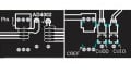
There's an eval kit available for the AD7768-1, shown below.

EVAL-AD7768-1. Image from Analog Devices
If you have any experience with the AD7768-1 or similar parts, such as the AD7768, please let us know in the comments below.